HVAC / Thermostats & Controls
Danfoss Redia RA click Thermostatic Sensor
Quick installation and configuration guide for the Danfoss Redia RA click thermostatic sensor. Learn how to install, set temperature limits, and apply theft protection.
Table of contents
Manual images
Click an image to enlargeQuick guide from the manual
The Danfoss Redia RA click is a thermostatic sensor designed for radiator valves. This guide covers standard installation, BIV installation, remote sensor setup, temperature limitation, and theft protection. Ensure the sensor is installed in a location with free air circulation for accurate temperature control.
Installation
The RA click system is designed for quick, tool-free mounting:
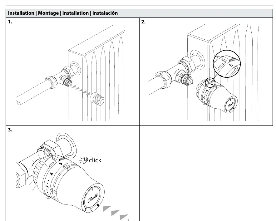
- Ensure the valve is fully open.
- Push the sensor firmly onto the valve body.
- Listen for a distinct 'click' sound, which confirms the sensor is securely locked in place.
BIV Installation
For BIV (Built-in Valve) installations:
- Remove the protective cap from the valve.
- Align the sensor with the valve.
- Push the sensor onto the valve until it clicks into position.
Remote Sensor Installation
If using a remote sensor version:
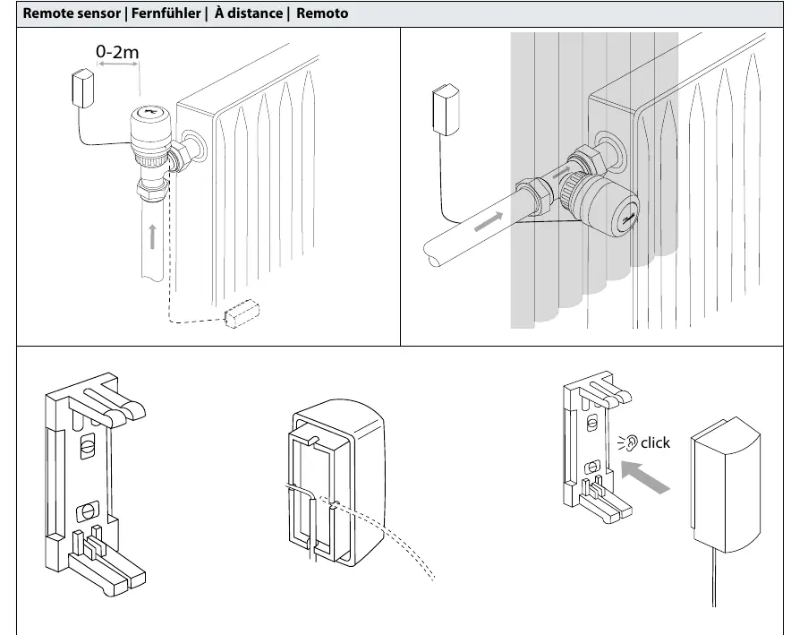
- The capillary tube allows for a distance of 0-2 meters between the sensor and the valve.
- Mount the remote sensor on the wall using the provided bracket.
- Ensure the sensor is not covered by curtains or furniture to allow proper air circulation.
Temperature Limitation
You can restrict the temperature range to prevent overheating or freezing:
Maximum Temperature Limitation
- Turn the dial to the desired maximum setting.
- Insert the limiter pin into the slot corresponding to the maximum temperature.
- The dial will now be physically restricted from turning past this point.
Minimum Temperature Limitation
- Turn the dial to the desired minimum setting.
- Insert the limiter pin into the slot corresponding to the minimum temperature.
- The dial will now be physically restricted from turning below this point.
Theft Protection
To prevent unauthorized removal of the sensor:
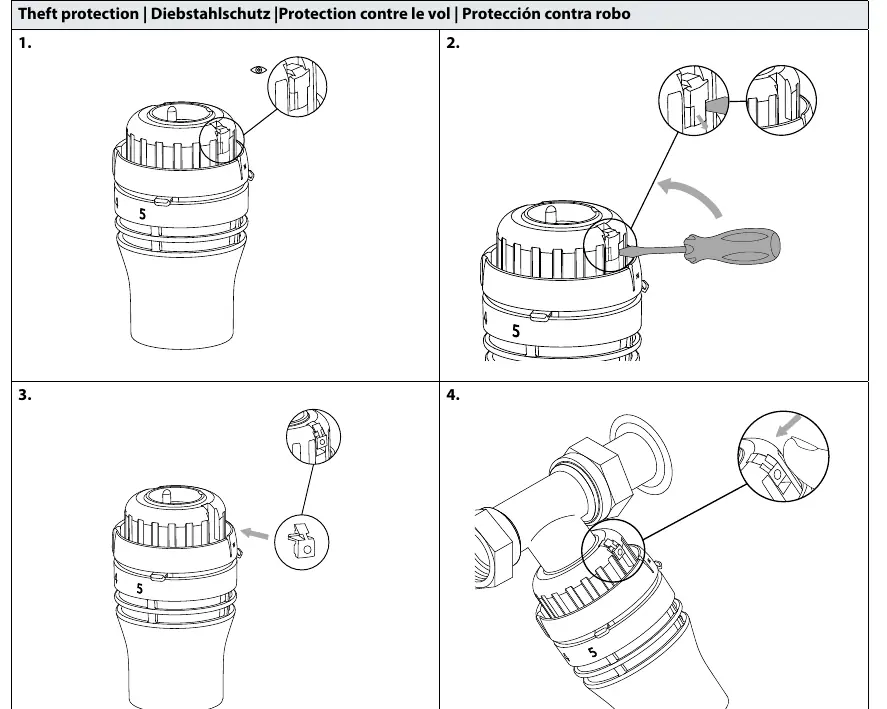
- Locate the theft protection slot on the sensor.
- Insert the locking screw or clip provided.
- Tighten or secure the locking mechanism to fix the sensor to the valve.
- To remove, reverse the process using a screwdriver to release the locking mechanism.
Manufacturer information
Danfoss A/S
Practical help
Common problems
Sensor does not lock onto the valve
Ensure the valve is fully open and push the sensor firmly until you hear a distinct 'click'.
Sensor is loose or can be easily removed
Verify that the 'click' mechanism has fully engaged. If theft protection is required, install the locking screw/clip.
Temperature adjustment range is too wide
Use the limiter pins to physically restrict the dial to your desired minimum or maximum settings.
Before use
- Verify the valve type is compatible with RA click.
- Ensure the installation area allows for free air circulation around the sensor.
- Check that the remote sensor capillary tube is not kinked or damaged (if applicable).
- Confirm the distance for the remote sensor is within the 0-2m range.
Images and diagrams
- The 'click' icon indicates the point where the sensor locks onto the valve.
- Limiter pins are small plastic tabs inserted into the dial to restrict rotation.
- The theft protection screw is inserted into the side of the sensor to lock it to the valve body.
Model compatibility
- Compatible with Danfoss RA click valve systems.

Manual page author
David Miller
Documentation analyst
Organizes user manual content into clear summaries, with attention to model details, product context, and everyday usability.