HVAC / Thermostats & Controls
Installation Guide for Danfoss Aveo RA click Thermostatic Sensor
A comprehensive installation and configuration guide for the Danfoss Aveo RA click thermostatic sensor. Includes step-by-step instructions for standard and BIV installation, uninstallation, and setting temperature limits.
Table of contents
Manual images
Click an image to enlargeQuick guide from the manual
This document provides essential instructions for installing, uninstalling, and configuring the temperature limits of the Danfoss Aveo RA click thermostatic sensor. Ensure you have the correct limiter clips (Code no. 013G1246) if you intend to restrict the temperature range.
Installation
The standard installation process is designed for quick mounting:
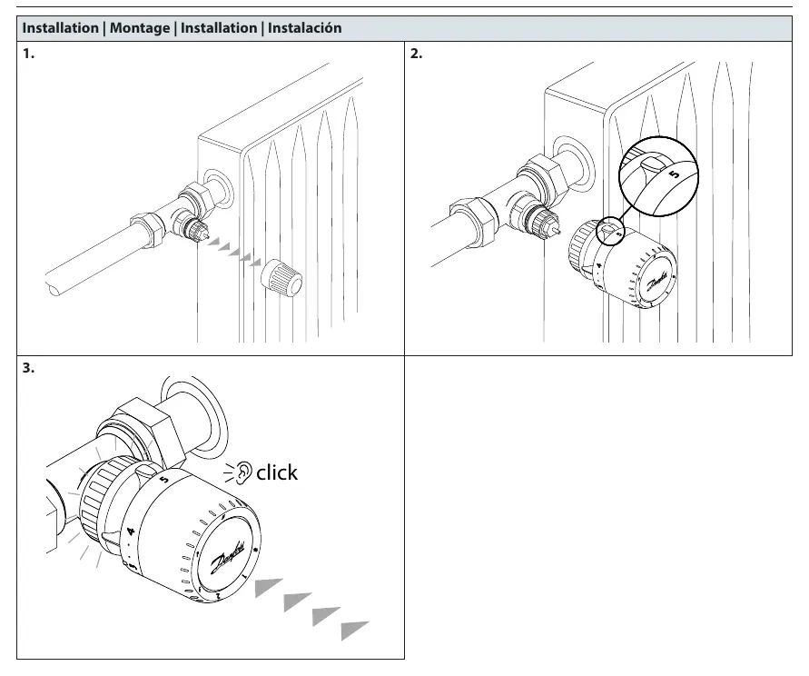
- Ensure the valve is clean and ready for the sensor.
- Align the sensor with the valve body.
- Push the sensor firmly onto the valve until you hear a distinct click, indicating it is securely locked in place.
BIV Installation
For Built-in Valve (BIV) configurations, follow these steps:
- Remove the protective cap from the valve.
- Align the sensor with the BIV interface.
- Push the sensor onto the valve until it clicks into position.
Uninstall
To remove the sensor from the valve:
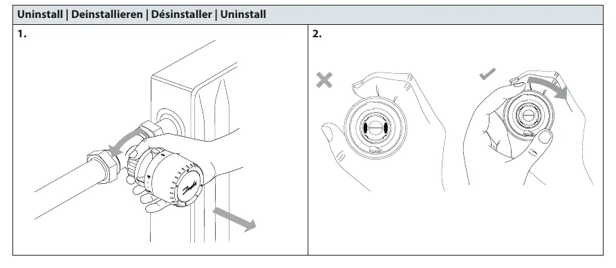
- Grip the sensor firmly.
- Rotate the sensor to unlock it from the valve body.
- Pull the sensor away from the valve.
Temperature Limitation
You can set maximum and minimum temperature limits using the limiter clips (Code no. 013G1246). The process is similar for both:
- Identify the desired temperature setting on the sensor dial.
- Insert the limiter clip into the corresponding slot on the sensor body.
- Use a small screwdriver if necessary to secure the clip in the desired position.
- For maximum limitation, set the clip to prevent the dial from turning past your chosen maximum value.
- For minimum limitation, set the clip to prevent the dial from turning below your chosen minimum value.
Blind mark
The sensor features a blind mark indicator to help align the setting with the index mark on the sensor body, ensuring accurate temperature selection.
Manufacturer information
Danfoss A/S
Practical help
Common problems
Sensor does not lock onto the valve
Ensure the valve is clean and the sensor is aligned correctly before pushing until the 'click' sound is heard.
Need to restrict temperature range
Use the limiter clips (Code no. 013G1246) to physically block the dial from turning past specific maximum or minimum settings.
Before use
- Verify the valve type is compatible with the RA click system.
- Ensure the valve is free of debris.
- Have a small screwdriver ready for temperature limiter installation.
- Confirm you have the correct limiter clips (013G1246) if temperature restriction is required.
Images and diagrams
- The 'click' icon indicates the successful locking of the sensor onto the valve.
- The screwdriver icon indicates where to insert the limiter clip for temperature adjustment.
- The 'MAX' and 'MIN' labels on the sensor dial indicate the range of temperature limitation.
Model compatibility
- Compatible with RA click valve systems.
- Suitable for standard and BIV (Built-in Valve) installations.

Manual page author
David Miller
Documentation analyst
Organizes user manual content into clear summaries, with attention to model details, product context, and everyday usability.