Hvac / Thermostats Controls
Installation Guide for Danfoss React RA click Thermostatic Sensor
Quick installation and configuration guide for the Danfoss React RA click thermostatic sensor, covering mounting, temperature limitation, and theft protection.
Table of contents
Manual images
Jump to the sectionQuick guide from the manual
This document provides essential instructions for the installation, temperature limitation, and security setup of the Danfoss React RA click thermostatic sensor series. It is intended for users performing initial setup or adjusting operational parameters.
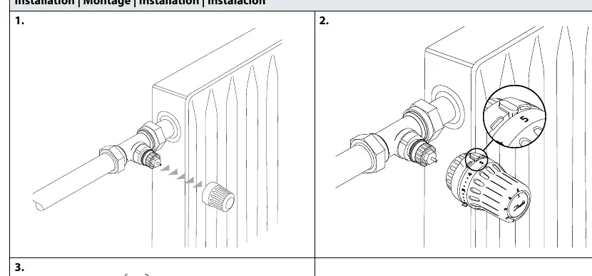
Installation
The sensor features a click-on mounting mechanism. Ensure the sensor is aligned correctly with the valve body. Push the sensor firmly onto the valve until you hear a distinct click, indicating it is securely locked in place.

BIV Installation
For BIV (Built-in Valve) configurations, follow the same alignment procedure. Ensure the sensor is properly seated on the valve interface and press until the click confirms a secure connection.
Uninstall
To remove the sensor, rotate the locking ring or follow the specific release mechanism indicated on the device to disengage it from the valve body.
Temperature Limitation
You can set maximum and minimum temperature limits to control the heating range:
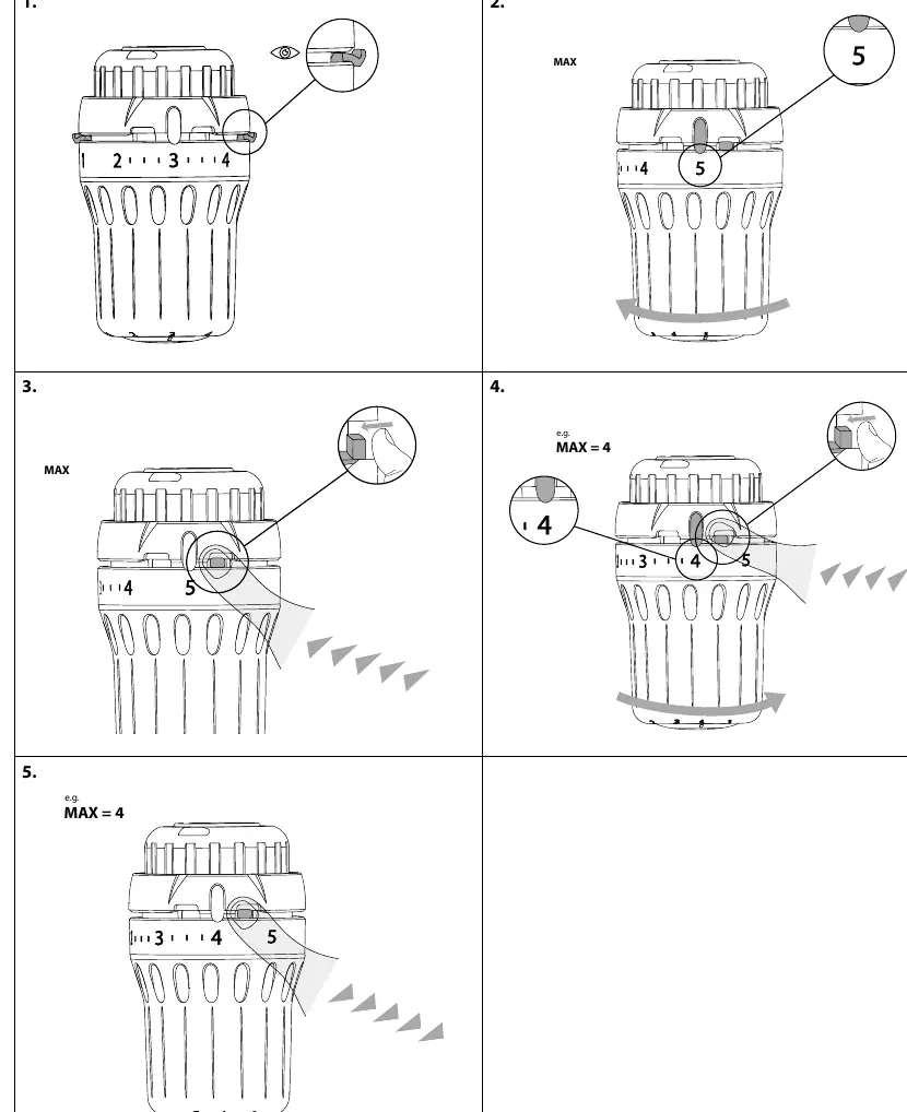
- Maximum Limitation: Rotate the sensor to the desired maximum setting. Use the internal adjustment mechanism to lock the limit, preventing the dial from being turned higher than the selected value.
- Minimum Limitation: Similarly, rotate the sensor to the desired minimum setting and engage the internal lock to prevent the dial from being turned lower than the selected value.
Theft Protection
The device supports optional theft protection to prevent unauthorized removal:
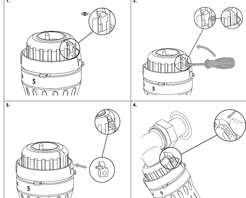
- Use the designated theft protection clip (Code no. 013G5245).
- Insert the clip into the sensor housing as shown in the diagrams.
- For removal, use the specialized tool (Code no. 013G1236) to disengage the security clip before attempting to remove the sensor from the valve.
Manufacturer information
Danfoss A/S
Practical help
Common problems
Sensor does not click into place
Ensure the sensor is correctly aligned with the valve body before applying pressure.
Cannot remove the sensor
Check if the theft protection clip is installed. If so, use the removal tool (013G1236) to disengage it first.
Before use
- Verify the valve body is compatible with the RA click system.
- Ensure the sensor is set to the desired initial temperature position.
- Check if theft protection is required for the installation environment.
Images and diagrams
- The 'click' sound indicates a successful mechanical lock.
- The 'MAX' and 'MIN' settings are adjusted using an internal tab mechanism.
- The 'Blind mark' indicates the alignment position for the sensor.
Model compatibility
- Designed for RA click valve systems.

Manual page author
Michael Turner
Technical manual editor
Reviews PDF manuals for structure, safety notes, and practical product details so readers can find the right information quickly.