Automotive / Car Audio
User Manual for Deaf Bonce Apocalypse Atom Pro Mono Amplifiers
Comprehensive user guide for the Deaf Bonce Apocalypse Atom Pro series mono amplifiers. Includes installation steps, wiring diagrams, impedance calculation, specifications, and troubleshooting.
Table of contents
Manual images
Click an image to enlargeQuick Start Guide
The Deaf Bonce Apocalypse Atom Pro series are high-performance Class D mono amplifiers. To ensure optimal performance and safety, follow these key steps:
- Disconnect the battery before starting any installation.
- Use appropriate cable gauges (AWG) based on the power consumption and cable length.
- Install a fuse within 40 cm of the battery positive terminal.
- Ensure minimum load impedance is 1 Ohm.
- Calibrate sound by setting the source volume to 3/4 and adjusting the amplifier gain until distortion is heard.
Safety Instructions
Proper installation is critical for safety and performance:
- Ensure the vehicle has a 12V DC electrical system with negative grounding.
- Do not install the amplifier in areas exposed to water, moisture, dust, or dirt.
- Ensure good air circulation around the amplifier; it can heat up to 80°C (176°F).
- Use high-quality copper speaker and power cables.
- Protect wires with rubber gaskets when passing through metal plates.
- Do not screw the amplifier directly to the metal chassis to avoid signal distortion.
Installation Sequence
- Disconnect the battery from the electrical system.
- Route the power cable from the battery to the amplifier location.
- Connect the power supply with correct polarity (+12V and GND).
- Install a fuse holder within 40 cm of the battery positive terminal. Do not install the fuse yet.
- Route signal cables (RCA) separately from power cables.
- Connect the RCA input (0.2V - 6V signal).
- Fasten the amplifier securely in the vehicle.
- Check all wiring connections.
- Install the fuse. Use a 12V 21W light bulb in series with the positive lead to test for shorts (the bulb should light briefly and go out).
- Connect the REM IN terminal to the head unit's remote output to activate the amplifier.
Wiring and Connections
The amplifier requires a solid power connection and correct speaker wiring:
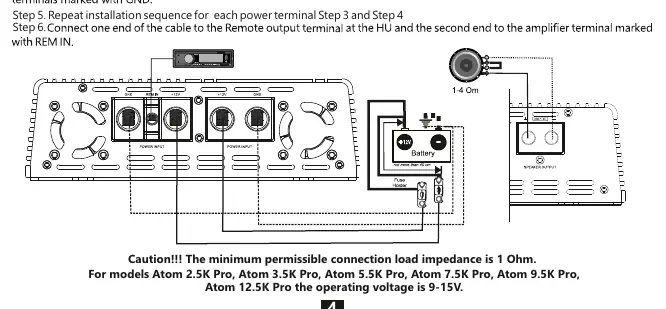
- Power Input: Connect +12V and GND terminals to the battery.
- Speaker Output: Connect speaker cables to the terminals marked SPEAKER OUTPUT.
- Remote Input (REM IN): Connect to the head unit's remote output to turn the amplifier on/off.
- RCA Input: Connect to the head unit's low-level outputs.
Controls and Adjustments
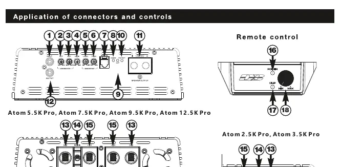
- GAIN: Adjusts input signal level (0.2V - 6V).
- CROSSOVER (HPF/LPF): Filters frequencies to match your subwoofer/speaker setup.
- BASS BOOST: Adjusts bass level (0-12 dB) and frequency (35-90 Hz).
- LED Indicators: Blue indicates operation; Red indicates protection mode; Orange indicates clipping.
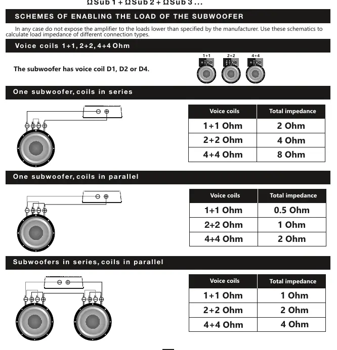
Impedance and Connection Methods
The minimum permissible load impedance is 1 Ohm. Use the provided formulas and diagrams to calculate total impedance based on your subwoofer voice coil configuration (series or parallel). Never expose the amplifier to loads lower than 1 Ohm.
Troubleshooting
- Amplifier does not turn on: Check all contacts, ensure 9-15V is present at terminals, and verify the REM IN signal.
- Amplifier goes into protection: Check for short circuits at the output, verify voice coil wiring, ensure impedance is not below 1 Ohm, and check supply voltage.
- No sound: Check RCA cable integrity, head unit settings, and speaker connections.
Specifications
The Atom Pro series includes models from 2.5K to 12.5K. All models operate on 9-15V and feature a 12 dB/Oct crossover. Refer to the full specifications table in the manual for detailed power ratings at 4, 2, and 1 Ohm loads.
Practical help
Common problems
Amplifier does not turn on
Check all contacts, verify 9-15V supply at terminals, and ensure REM IN receives +12V.
Amplifier goes into protection mode
Check for short circuits at the speaker output, verify correct voice coil wiring, ensure impedance is >= 1 Ohm, and check supply voltage.
No sound from speakers/subwoofer
Check RCA cable connections, head unit output, and speaker wiring integrity.
Amplifier goes into protection at high volume
Ensure the alternator and battery can supply enough current. Check for overheating and verify load impedance.
Before use
- Disconnect the vehicle battery.
- Use appropriate AWG power cables.
- Install a fuse within 40cm of the battery.
- Ensure minimum load impedance is 1 Ohm.
- Route signal cables separately from power cables.
Specs in practice
- Input Sensitivity
- Voltage range (0.2V-6V) for matching the head unit's output signal.
- Damping Factor
- Ability of the amplifier to control speaker cone movement.
Images and diagrams
- Standard wiring diagram: Shows power, ground, remote, and RCA connections.
- Impedance calculation: Formulas for series and parallel subwoofer connections.
Model compatibility
- Minimum load impedance: 1 Ohm.
- Operating voltage: 9-15V.

Manual page author
Michael Turner
Technical manual editor
Reviews PDF manuals for structure, safety notes, and practical product details so readers can find the right information quickly.