Automotive / Car Audio
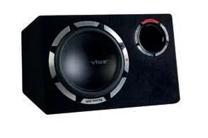
User Manual for VIBE PULSE CBR 12A Active Bass Reflex Subwoofer
Quick guide for the VIBE PULSE CBR 12A active bass reflex subwoofer. Includes installation, wiring, setup, gain control, crossover settings, and troubleshooting.
Table of contents
Manual images
Click an image to enlargeQuick guide from the manual
The VIBE PULSE CBR 12A is an active bass reflex subwoofer designed for automotive audio systems. This manual covers the installation, wiring, and setup procedures required to achieve optimal performance. Key features include an Autosense circuit for automatic turn-on via high-level inputs and adjustable crossover and gain controls.
Safety and Warnings
- Heat Warning: The amplifier heatsink can become very hot during use. Do not touch it during or immediately after operation. Ensure it does not come into contact with heat-sensitive materials like upholstery or plastics.
- Electrical Load: An aftermarket amplifier adds load to the vehicle's charging system. Ensure your vehicle's electrical system can handle the load.
- Hearing Safety: This equipment is capable of high sound pressure levels that can cause permanent hearing damage. Use common sense and practice safe listening.
Installation Guidelines
For the best results, mount the enclosure in the luggage compartment of the vehicle.
- Location: Mount in a dry location on a solid surface.
- Airflow: Ensure at least two inches of clearance around the casing for proper ventilation.
- Orientation: Never mount the enclosure upside down, as this will cause the amplifier to overheat.
- Positioning: Experiment with positioning; facing the rear bumper often produces deeper bass than firing into the rear seat.
- Security: Ensure the enclosure is securely mounted to prevent movement. Use additional luggage straps if necessary.
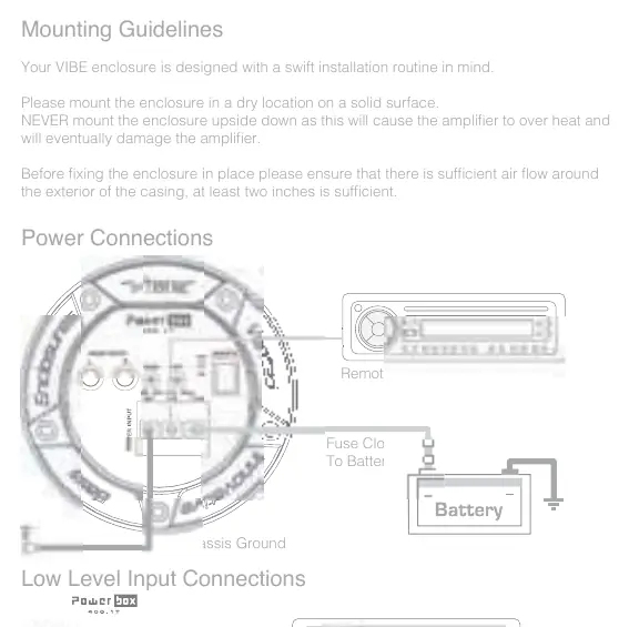
Power and Input Connections
Proper wiring is essential for performance and safety.
- Power Cable: Use at least 10 gauge cable. Connect directly to the battery. Use rubber grommets when passing through bulkheads.
- Fuse: Install a fuse or circuit breaker inline with the power cable, no further than 18 inches from the battery. The fuse rating should match the amplifier's internal fuse.
- Ground Cable: Use at least 10 gauge cable. Connect directly to bare metal on the vehicle chassis. Keep the cable length to a minimum.
- Inputs: The unit supports both low-level (RCA) and high-level (speaker wire) inputs.
- Autosense: When using high-level inputs, the amplifier turns on automatically without a remote wire. For low-level (RCA) inputs, a remote turn-on wire from the headunit is required.
Setup and Configuration
Gain Control Setting
- Turn the gain control to minimum.
- Set headunit crossovers to flat and bass/treble to zero.
- Turn the headunit volume to approximately 3/4.
- Slowly increase the gain on the amplifier until distortion is heard, then turn it down slightly.
Crossover Setting
The frequency control is adjustable between 30Hz and 150Hz. Use this to blend the subwoofer frequencies with the rest of the vehicle's speakers so the bass integrates naturally.
Run In Procedure
New subwoofers are stiff and require a run-in period to reach full potential.
- For the first 30 hours, play the subwoofer at low to medium volumes.
- Gradually increase the volume over time.
Troubleshooting
- Amplifier will not power up: Check ground connections, ensure remote wire has +12V, verify battery voltage is between 12V and 16V, and check all fuses.
- Protection LED illuminated: Check for cable shorts. The amplifier will shut down if it reaches 80°C. If it does not restart after cooling, the unit may be damaged.
- Distorted sound: Reduce the gain control setting.
- Blown fuses: Check positive and ground cables for shorts and ensure the correct external fuse is fitted (20A for CBR12A).
Practical help
Common problems
Amplifier will not power up
Check ground connection, remote wire voltage (+12V), battery voltage (12-16V), and all fuses.
Protection LED illuminated
Check for cable shorts. Ensure the amplifier is not overheating (80°C limit). If it does not restart, the unit may be damaged.
Distorted sound
Reduce the gain control setting on the amplifier.
Blown fuses
Check positive and ground cables for shorts and ensure the correct external fuse is fitted (20A for CBR12A).
Before use
- Ensure the enclosure is mounted in a dry location on a solid surface.
- Provide at least two inches of clearance around the casing for airflow.
- Use at least 10 gauge cable for power and ground connections.
- Install a fuse/circuit breaker inline with the power cable, no further than 18 inches from the battery.
- Connect the ground cable directly to bare metal on the vehicle chassis.
Specs in practice
- Peak/RMS Power
- 900W/300W - Maximum and continuous power handling capacity.
- Configuration
- 4th order bass reflex - The type of enclosure design.
- Frequency Control
- 30Hz - 150Hz - Adjustable crossover range to blend bass frequencies.
Images and diagrams
- Wiring diagram shows connections for power (battery, fuse, ground), remote turn-on, and audio inputs (RCA or high-level).
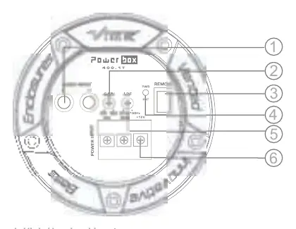
- Terminals diagram identifies inputs, gain control, remote level port, LED indicators, LPF, and power terminals.
Model compatibility
- Autosense feature allows auto turn-on without a remote wire when using high-level inputs.
- For low-level (RCA) inputs, a remote turn-on wire from the headunit is required.

Manual page author
Michael Turner
Technical manual editor
Reviews PDF manuals for structure, safety notes, and practical product details so readers can find the right information quickly.