Automotive / Car Audio
VIBE BlackBox Stereo 2 / Stereo 4 / Bass 1 Power Amplifier User Manual
Quick guide for VIBE BlackBox Stereo 2, Stereo 4, and Bass 1 power amplifiers. Includes installation, wiring diagrams, setup instructions, troubleshooting, and technical specifications.
Table of contents
Manual images
Click an image to enlargeQuick guide from the manual
This manual covers the installation, setup, and operation of the VIBE BlackBox series amplifiers (Stereo 2, Stereo 4, and Bass 1). Proper installation is critical for performance and safety. Always ensure the amplifier is mounted in a dry location on a solid surface with at least two inches of airflow around the casing. Never mount the amplifier upside down.
Mounting and Connections
Mounting: Ensure the amplifier is mounted on a solid surface in a dry location. Maintain at least two inches of clearance around the casing for proper ventilation.
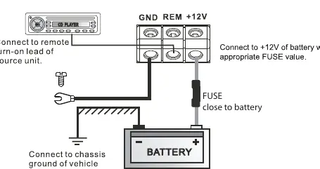

Power and Ground: Use at least an 8-gauge cable for both power and ground. The ground cable must be connected directly to the vehicle chassis at a bare metal point. A fuse or circuit breaker of equal value to the amplifier's rating must be installed inline with the power cable, no further than 18 inches from the battery.
Remote Turn-On: Use a minimum of 18-gauge cable. If the head unit lacks a remote turn-on lead, a 12V supply with an inline switch can be used.
RCA Cables: Run RCA cables on the opposite side of the vehicle from power cables to minimize interference.
Setup Section
To correctly set the gain control:
- Turn the gain control to minimum on the amplifier.
- Set bass boost to 0 dB.
- Set head unit crossovers to flat and bass/treble to zero.
- Turn the head unit volume to approximately 3/4.
- Slowly increase the amplifier gain until distortion is heard, then back it off slightly.
Crossover Settings
- Subwoofer: Set to Low Pass (typically 60-120Hz).
- Full Range Speakers: Set to Flat.
- Speakers with Passive Crossover: Set to High Pass (typically 40-120Hz).
Troubleshooting
- Amplifier won't power up: Check ground connections, ensure remote terminal has at least 7V, check battery voltage (min 10.5V), and inspect all fuses.
- Protection LED on: Check for speaker wire shorts and ensure the amplifier is not overheating (auto-shutdown occurs above 80°C).
- Amplifier gets hot: Verify minimum speaker impedance and ensure adequate airflow.
- Distorted sound: Check gain settings, crossover frequencies, and speaker wiring/polarity.
Practical help
Common problems
Amplifier will not power up
Check ground connections, ensure remote terminal has at least 7V, check battery voltage (min 10.5V), and inspect all fuses.
Protection LED illuminates
Check for shorts on speaker wires and ensure the unit is not overheating (above 80°C).
Amplifier gets very hot
Verify minimum speaker impedance is correct, check for speaker shorts, and ensure adequate airflow.
Distorted sound
Reduce gain control, verify crossover frequencies, and check speaker wiring/polarity.
Before use
- Mount in a dry location on a solid surface
- Ensure at least 2 inches of airflow around the casing
- Use at least 8 gauge cable for power and ground
- Install a fuse/circuit breaker within 18 inches of the battery
- Test speaker wiring before final installation
Specs in practice
- Low Pass Filter
- Frequency range for subwoofer output (30-300Hz or 40-250Hz).
- High Pass Filter
- Frequency range for full-range speakers (50Hz-1kHz).
- Subsonic Filter
- Filters out very low frequencies (15-50Hz) to protect subwoofers.
Images and diagrams
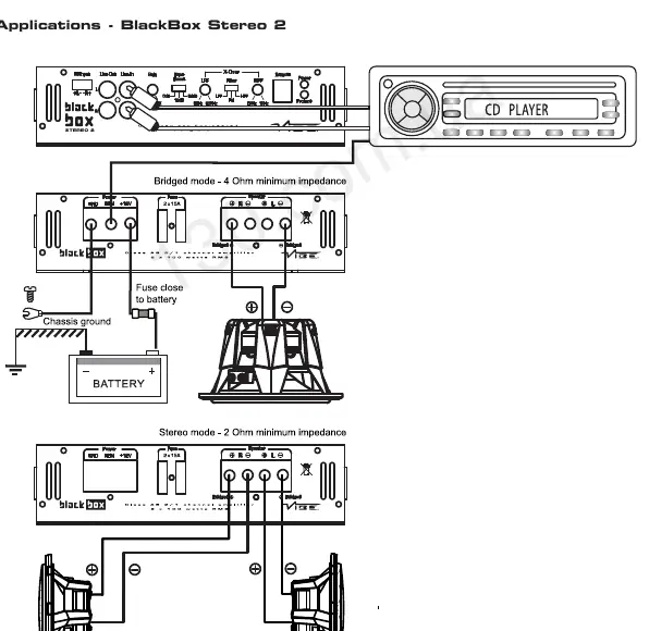
- Wiring diagram for power, ground, and remote turn-on
- Speaker wiring examples for bridged and stereo modes
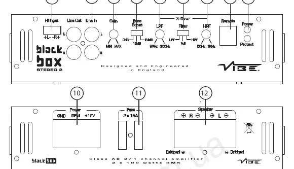
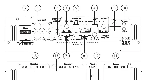
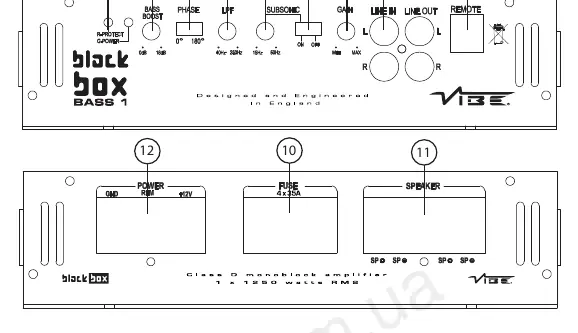
- Control panel layout for Stereo 2, Stereo 4, and Bass 1 models
Model compatibility
- Stereo 2: 2 Ohm stereo / 4 Ohm bridged
- Stereo 4: 2 Ohm stereo / 4 Ohm bridged
- Bass 1: 1 Ohm minimum impedance

Manual page author
Michael Turner
Technical manual editor
Reviews PDF manuals for structure, safety notes, and practical product details so readers can find the right information quickly.