Plumbing / Sinks Faucets
Delta 15718LF Lakewood Single Handle Lavatory Centerset Faucet
A comprehensive installation and maintenance guide for the Delta 15718LF Lakewood single-handle lavatory faucet. Includes step-by-step instructions for mounting, water supply connection, pop-up assembly, system flushing, and...
Table of contents
Manual images
Click an image to enlargeQuick Guide from the Manual
This document provides installation and maintenance instructions for the Delta 15718LF Lakewood single-handle lavatory faucet. Before beginning, ensure you have the necessary tools, including a wrench, pliers, and silicone sealant. The installation process involves mounting the faucet, connecting water supplies, assembling the pop-up drain, and flushing the system to remove debris.
Faucet Installation
The faucet is designed for single or three-hole installations. Follow these steps to mount the unit:
- Position the faucet (1) with the escutcheon (2) and gasket (3) on the mounting surface.
- If the mounting surface is uneven, apply silicone sealant under the gasket (3).
- Place the mounting hardware (4) over the mounting stud under the sink.
- Secure the faucet using the mounting nut (6). Tighten the nut securely.
Connecting Water Supplies
Determine the type of connection required for your plumbing setup:
- Ball nose risers: Use 3/8 inch O.D. copper tubing with coupling nuts (not provided).
- I.P.S. connectors: Use 1/2 inch I.P.S. faucet connectors.
Pop-Up Assembly
Follow these steps to install the pop-up drain mechanism:
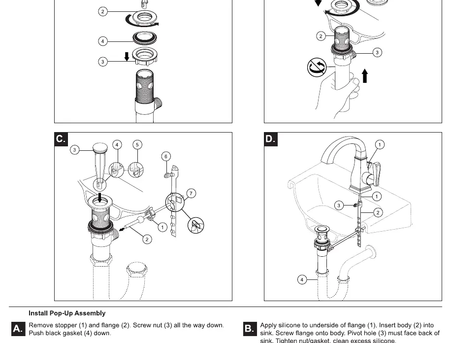
- Remove the stopper (1) and flange (2). Screw the nut (3) all the way down and push the black gasket (4) down.
- Apply silicone to the underside of the flange (1) and insert the body (2) into the sink. Screw the flange onto the body. Ensure the pivot hole (3) faces the back of the sink. Tighten the nut/gasket and clean excess silicone.
- Remove the pivot nut (1). Install the horizontal rod (2) and stopper (3) as removable (4) or non-removable (5). Hand-tighten the pivot nut (1).
- Attach the horizontal rod to the strap (7) using the clip.
- Insert the lift rod (1) through the faucet and into the strap (2). Tighten the screw (3) and connect the assembly to the drain (4).
Flush System and Check for Leaks
After installation, it is critical to flush the system to prevent debris from damaging internal parts:
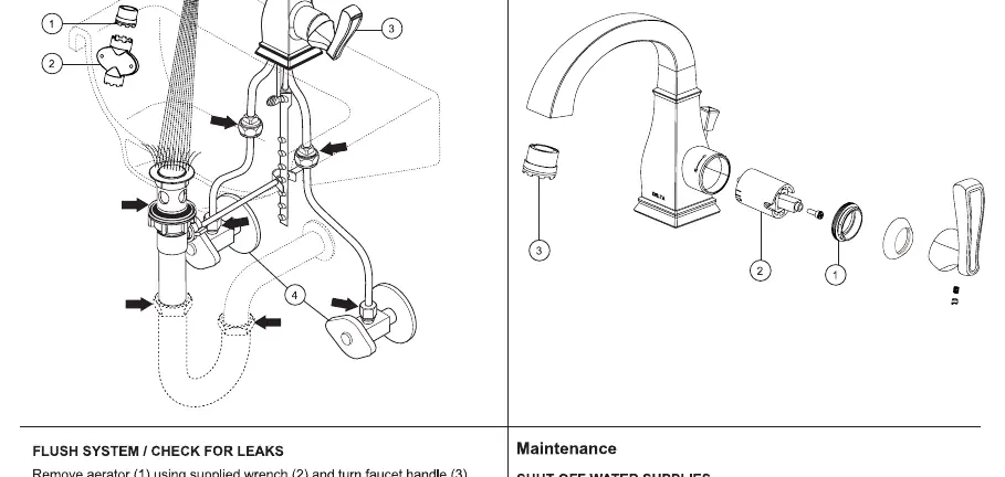
- Remove the aerator (1) using the supplied wrench.
- Turn the faucet handle (3) to the full mix position.
- Slowly turn on the hot and cold water supplies and flush the lines for one minute.
- Check all connections for leaks and re-tighten if necessary.
Maintenance and Cleaning
To keep the finish in good condition, wipe gently with a damp cloth and blot dry with a soft towel. Avoid harsh abrasives or polishes.
Troubleshooting
- Faucet leaks under handle: Remove the handle and ensure the bonnet (1) is tight. If the leak persists, replace the cartridge (2).
- Faucet leaks from spout: Replace the cartridge (2).
- Low flow: Remove and clean the aerator (3).
Practical help
Common problems
Faucet leaks under the handle
Ensure the bonnet is tight. If the leak persists, replace the cartridge.
Faucet leaks from the spout
Replace the cartridge.
Very low water flow
Remove and clean the aerator.
Before use
- Ensure you have a wrench, pliers, and silicone sealant.
- Verify the mounting surface is clean and level.
- Determine if you need 3/8 inch O.D. copper tubing or 1/2 inch I.P.S. connectors.
- Ensure water supply is turned off before starting installation.
Specs in practice
- 3/8 inch O.D. copper tubing
- Standard size for ball nose riser water supply connections.
- 1/2 inch I.P.S.
- Standard size for faucet supply connectors.
Images and diagrams
- Step 1A/1B: Shows the mounting process for the faucet body and gasket.
- Step 2: Illustrates the connection points for water supply lines.
- Step 3: Details the assembly of the pop-up drain stopper and rod mechanism.
- Step 4: Shows the aerator removal and flushing process.
Model compatibility
- Compatible with single or three-hole sink configurations.

Manual page author
David Miller
Documentation analyst
Organizes user manual content into clear summaries, with attention to model details, product context, and everyday usability.