Power / Power Conditioning
Operation Manual for Delta 100kW Power Conditioning System
Quick guide for the Delta 100kW Power Conditioning System (PCS). Learn how to operate the system, use the HMI tool, configure parameters, and troubleshoot faults.
Table of contents
Manual images
Click an image to enlargeQuick Start Guide
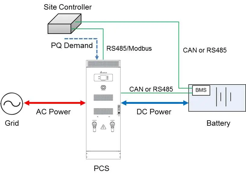
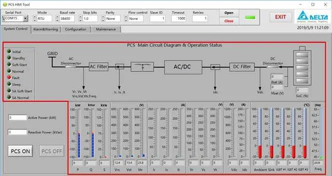
The Delta 100kW Power Conditioning System (PCS) is designed for grid-tie or standalone operation. To power on the system, ensure the upstream breaker is closed, then turn the AC and DC switches on the front door to the ON position. The system will enter standby mode. To fully start the system, use the PCS HMI Tool on a connected PC and press the PCS ON button.
To power off the system, ensure it is not in a Soft-Start or Run state. Use the PCS HMI Tool to switch the system to Standby mode, then turn the AC and DC switches on the front door to the OFF position.
Front Panel Operation
The front panel features an LCD screen, function buttons, and LED indicators. The LEDs provide immediate status: STANDBY (yellow), RUN (green), and FAULT (red). The function buttons allow navigation through various menus, including Ratings, Alarm, Battery, and Info. Note that the ON/OFF buttons on the LCD panel are disabled; system control must be performed via the HMI software.
PCS HMI Tool
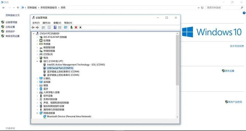
The PCS HMI Tool is required for remote monitoring, testing, and configuration. It is compatible with Windows 7 SP1 through Windows 10. Connection is established via an RS485-USB converter. Ensure the correct COM port is selected in the device manager and configured within the HMI software. The software allows for real-time monitoring of grid voltage, current, battery status, and power output.
System Configuration
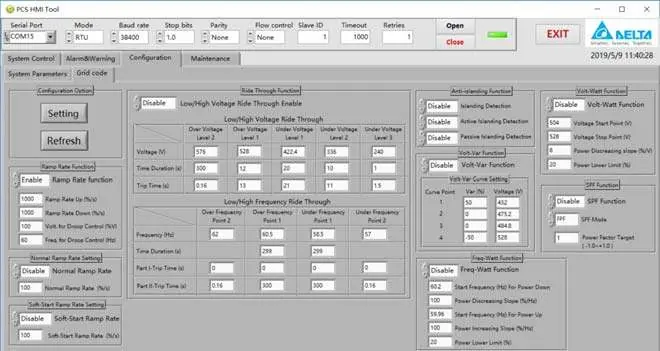
Parameters can only be configured when the PCS is in the OFF state. Use the HMI Tool to read and write settings. Configuration is divided into System Parameters (rated operating parameters, running mode, threshold settings) and Grid Code Parameters (adjustments for local grid regulations). Always click the Refresh button to read current values before modification and click Setting to apply changes.
Maintenance and Fault Logs
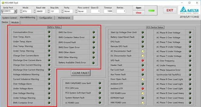
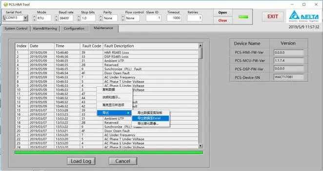
The maintenance interface allows users to view the PCS serial number, firmware versions, and fault logs. Fault logs can be exported to Excel for analysis. If a system error occurs, the fault name is displayed on the HMI screen. Detailed fault definitions are provided in the appendix, categorized by fault type (e.g., MCU Vac Fault, MCU Batt Fault, DSP Conv Fault).
Practical help
Common problems
HMI Com Loss
Check the connection between the PCS internal controller and the HMI. Ensure the RS485 cable is properly connected.
Device not responding to HMI commands
Verify the RS485 polarity. If the device does not respond, try reversing the Data (+) and Data (-) lines.
Cannot configure parameters
Ensure the PCS is in the 'OFF' state. Configuration is disabled while the system is running.
Before use
- Ensure the upstream breaker is in the closed state.
- Verify that AC and DC switches on the front door are in the ON position.
- Install the PCS HMI Tool on a PC (Windows 7-10).
- Connect the RS485-USB converter to the PC and the PCS.
- Verify the COM port number in the device manager.
Specs in practice
- Active Power (kW)
- The active power demand of the system. Positive values indicate power sourced to the grid; negative values indicate power sunk from the grid.
- Reactive Power (kVar)
- The reactive power demand of the system. Positive values indicate reactive power sourced to the grid; negative values indicate reactive power sunk from the grid.
Images and diagrams
- Figure 9: Demand Mode connection diagram showing the relationship between the Site Controller, PCS, Grid, and Battery.
- Figure 26: Connection diagram for linking the PCS to a PC using an RS485-USB converter.
Model compatibility
- Compatible with VDE-AR-N4105 and AS/NZS 4777.2 grid codes.
- HMI Tool requires Windows 7 SP1 to Windows 10.

Manual page author
Emily Carter
User documentation editor
Prepares concise manual descriptions and highlights the most useful setup, operation, and maintenance information for readers.