Tools / Saws
Instruction Manual for Delta 12-inch Sliding Compound Miter Saw 26-2312
Quick guide for the Delta 12-inch Sliding Compound Miter Saw 26-2312. Includes setup, adjustment, operation, maintenance, and troubleshooting instructions.
Table of contents
Manual images
Click an image to enlargeQuick guide from the manual
This manual provides essential information for the safe and efficient operation of the Delta 12-inch Sliding Compound Miter Saw (Model 26-2312). Always read and understand all safety warnings before use. Keep the saw on a stable, level surface and ensure the work area is clean and well-lit. Always wear eye protection and keep hands at least 4 inches away from the blade.
Safety Instructions
General Safety: Never operate the saw in explosive atmospheres or wet conditions. Always disconnect the power before making adjustments or changing accessories. Do not force the tool; use the correct tool for the application.
Miter Saw Specifics: Never cross your hands over the cutting line. Always clamp the workpiece securely against the fence and table. Never cut freehand. Ensure the saw head is locked in the down position for storage and transport only, never during operation.
Assembly
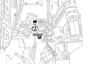
Work Clamp: Insert the clamp shaft into either hole on the miter base, slide the arm to touch the workpiece, and rotate the knob clockwise to secure.
Dust Bag: Attach the dust bag over the dust port on the upper blade guard.
Blade Installation: Ensure the saw is unplugged. Raise the saw arm, rotate the lower blade guard to expose the blade bolt, and use the provided T30 Torx/Blade Wrench to remove the bolt (left-hand threads). Align the new blade with the spindle, ensuring teeth face down at the front, and secure the bolt.
Adjustments
Bevel Alignment: With the saw unplugged, set the miter to 0 degrees and bevel to 0 degrees. Place a combination square against the table and blade face. If not flush, loosen the three screws on the bevel scale and adjust until flush.
Miter Alignment: Set the miter to 0 degrees. Place a framing square against the fence and blade face. If not flush, loosen the four screws on the miter table and adjust until flush.
Depth Stop: Flip the depth stop plate counterclockwise to the down position. Adjust the depth stop screw to the desired depth and lock with the wing-nut.
Operation
Cutting Procedures: Always ensure the workpiece is supported. For warped material, place the convex face against the fence. For slide cuts, push the saw head away from you and toward the back of the saw, stopping at the fully retracted position.
Crown Molding: For a 90-degree corner, lay the molding flat on the miter table against the fence. Set the bevel angle to 33.85 degrees and the miter angle to 31.62 degrees (left or right depending on the cut).
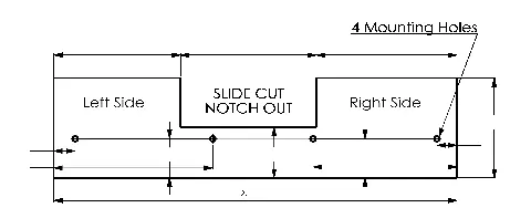
Auxiliary Fence: For larger workpieces, attach a 3/4-inch thick wood auxiliary fence using the pre-drilled mounting holes. A notch must be cut out for slide cuts.
Maintenance
Cleaning: Periodically blow out air passages with dry compressed air. Clean plastic parts with a soft, damp cloth; do not use solvents.
Brush Replacement: If brushes have less than 1/4 inch of carbon remaining, replace them. Remove the motor end cap, unscrew the brush cap, remove the old assembly, and insert new brushes, ensuring the curvature matches the motor.
Troubleshooting
If the saw fails to start, check the power connection, fuse/circuit breaker, or worn brushes. If the saw makes poor cuts, check the blade sharpness, mounting, or clean residue from the blade.
Practical help
Common problems
Saw will not start
Check if the saw is plugged in, reset the circuit breaker/fuse, or contact a service center to replace worn brushes.
Saw makes poor cuts
Replace the dull blade, ensure the blade is mounted correctly, or clean residue from the blade.
Machine has excessive vibration
Tighten all mounting hardware, ensure the saw is on a level surface, or replace a damaged blade.
Miter cuts are not accurate
Check and adjust the miter scale and ensure the blade is square to the fence and perpendicular to the table.
Before use
- Ensure the saw is unplugged before performing any adjustments.
- Verify the blade is sharp and mounted correctly.
- Check that all guards are in place and moving freely.
- Ensure the workpiece is clamped securely against the fence and table.
- Verify the miter and bevel locks are tightened before cutting.
- Perform a simulated cut without power to check for interference.
Specs in practice
- Blade Diameter
- 12 inch (305mm) is the required size.
- No Load Speed
- 4,000 r/min (RPM).
Images and diagrams
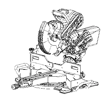
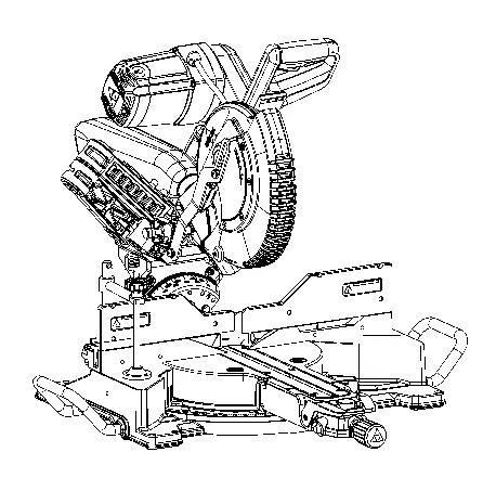
- Figure 1: Main components and controls identification.
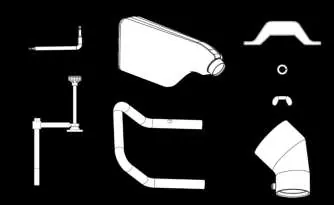
- Figure 3: Package contents list.
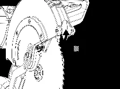
- Figure 8-10: Blade installation and removal procedure.
- Figure 12-14: Bevel and Miter alignment adjustments.
- Figure 38: Auxiliary fence dimensions.
Model compatibility
- Use only 12-inch blades rated for 4,000 RPM or higher.
- Do not use abrasive cut-off wheels for ferrous materials.
- Requires a 120V, 60Hz power supply.
- Auxiliary fence should be made of 3/4-inch thick wood.

Manual page author
Michael Turner
Technical manual editor
Reviews PDF manuals for structure, safety notes, and practical product details so readers can find the right information quickly.