Tools / Saws
User Manual for Craftsman 12-Inch Band Saw/Sander
Comprehensive user guide for the Craftsman 12-Inch Band Saw/Sander (Models 113.243401 and 113.243411). Includes assembly instructions, motor setup, blade installation, sanding attachment, maintenance, and troubleshooting.
Table of contents
Manual images
Click an image to enlargeQuick Guide from the Manual
This manual provides instructions for the Craftsman 12-Inch Band Saw/Sander, covering models 113.243401 (Saw only) and 113.243411 (Saw with legs and motor). Before operating, ensure the machine is securely bolted to a stand or floor, wear ANSI Z87.1 compliant safety goggles, and verify that the blade teeth point downward. Always disconnect power before performing maintenance or changing accessories.
Assembly
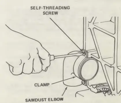
Installing Sawdust Elbow: Remove the band saw cover by applying pressure to the spring tabs. Attach the sawdust elbow to the opening at the bottom left-hand side of the saw using the provided clamp and self-threading screws.
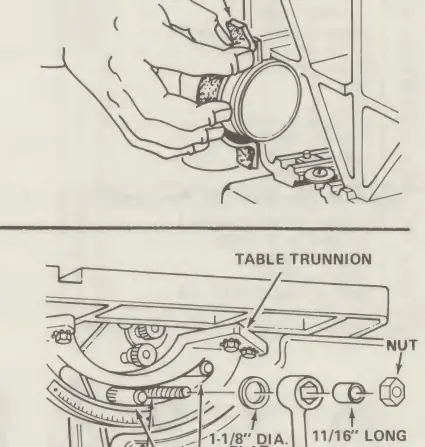
Installing Table: Apply automobile wax to the table. Place the table on the band saw, ensuring trunnion pins and the table lock bolt go through the slot. Secure with the flat washer, sleeve, and table lock handle.
Assembling Steel Legs: Assemble end and side stiffeners using truss head screws. Attach legs to the stiffeners. Install support channels and motor support. Level the unit using the leveling feet.
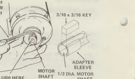
Motor and Belt Guard: Mount the motor to the support bracket. Install the belt guard support. Place the pulley on the motor shaft, ensuring the hub is flush with the end of the shaft. Install the belt and tension it by pushing downward on the motor before tightening the bolts.
Installing the Blade
1. Loosen the blade guard and guide bar lock screw. Position the upper guide assembly approximately three inches above the table.
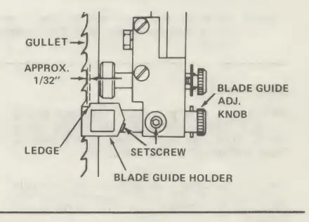
2. Loosen setscrews for upper and lower blade guides and thrust bearings.
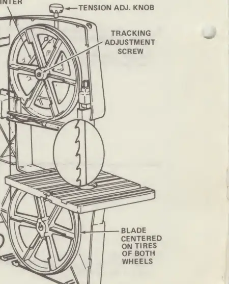
3. Place the blade over the wheels with teeth pointing downward. Ensure the blade is centered on the rubber tires.
4. Adjust the tension knob until the pointer aligns with the correct blade width (e.g., 1/4 inch).
5. Adjust tracking by turning the tracking adjustment screw until the blade runs in the center of the tire.
6. Adjust thrust bearings and blade guides to support the blade without pinching it.
Sanding Attachment
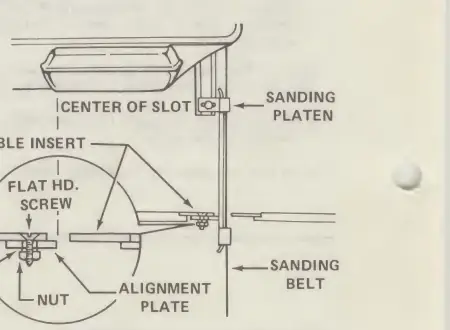
To convert the band saw to a sander, remove the blade guard, table insert, and blade. Install the sanding platen to the guide bar. Ensure the sanding belt's directional arrow matches the rotation. Adjust the platen and belt tracking similarly to the blade setup.
Operation
Sawing: Feed work into the blade using both hands, holding the workpiece firmly against the table. Do not force the work; allow the blade to cut. The minimum cutting diameter depends on the blade width.
Sanding: Press the workpiece gently against the sanding belt and keep it moving for a smooth finish.
Maintenance
- Tires: Remove pitch and sawdust with a stiff brush. Replace worn tires by stretching them around the wheels (do not glue).
- Cleaning: Keep the saw clean. Remove sawdust from the inside. Clean table, guides, and thrust bearings with Craftsman Gum and Pitch Remover.
- Lubrication: Ball bearings are factory-packed and require no further lubrication. Periodically oil the upper wheel guide rods.
Manufacturer information
CRAFTSMAN
Practical help
Common problems
Motor will not run
Check for a defective switch, cord, or receptacle. If the motor has an overload protector, it may be open.
Blade does not run in the center of the wheel
Adjust the tracking screw (upper wheel) or reposition the lower wheel on the shaft.
Band saw slows down when cutting
Check if the belt is too loose, the motor is pivoting, the cutting radius is too small, or the blade is dull.
Blades breaking
Reduce blade tension or avoid cutting too small a radius.
Before use
- Ensure the machine is bolted securely to a stand or floor.
- Wear safety goggles complying with ANSI Z87.1.
- Verify the blade teeth point downward.
- Check that blade tension, guides, and thrust bearings are properly adjusted.
- Ensure the switch is in the OFF position before plugging in.
- Clear the table of all objects except the workpiece.
Specs in practice
- Minimum Circle
- Determined by blade width; a 1/4 inch blade cuts a minimum diameter of approximately 1-1/2 inches.
Images and diagrams
- Exploded views for assembly and repair parts.
- Wiring diagram for motor connection.
- Adjustment diagrams for blade tracking and guide alignment.
Model compatibility
- Model 113.243401: Saw only.
- Model 113.243411: Includes steel legs and motor.
- Do not convert to 230V operation.

Manual page author
David Miller
Documentation analyst
Organizes user manual content into clear summaries, with attention to model details, product context, and everyday usability.