HVAC / Thermostats & Controls
Installation Guide for DEVIreg Solo Thermostat
A comprehensive installation and setup guide for the DEVIreg Solo programmable indoor thermostat. This manual covers mounting, wiring, floor sensor installation, initial configuration, error code troubleshooting, and technical...
Table of contents
Manual images
Click an image to enlargeQuick guide from the manual
The DEVIreg Solo is a programmable thermostat designed for electric floor heating. This guide provides essential steps for installation, wiring, and initial setup. Always ensure the mains power is disconnected before starting any electrical work.
Installation
The thermostat is designed for wall mounting in standard EU boxes. Follow these guidelines for optimal performance:
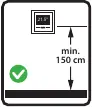

- Placement: Install at an appropriate height, typically 150 cm. Avoid direct sunlight, heating appliances, or poorly insulated exterior walls. Keep at least 50 cm away from windows and doors.
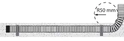
- Floor Sensor: Installation of a floor sensor is recommended and mandatory for wooden or similar floor constructions. Ensure the sensor is placed in a conduit pipe with a bending radius greater than 50 mm, positioned midway between two heating cables.
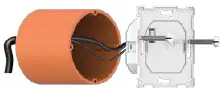
- Mounting: Secure the power supply unit to the wall box using at least two screws. Ensure the unit is oriented correctly using the UP arrow. Attach the frame and front display by pressing lightly until firmly connected.
Wiring
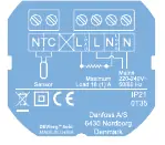
Ensure the electric circuit is de-energized before connecting. Connect wires according to the wiring diagram on the back of the power supply unit. The screen/PE wire from the heating element must be connected to the PE wire from the main power supply using a separate connector. Ensure all terminals are properly fastened.
Initial Setup
Upon first activation, the thermostat will guide you through a setup wizard:
- Language: Select your preferred language.
- Time & Date: Set the current time and date.
- Flooring Type: Select the flooring material (e.g., Wood).
- Control Mode: Choose between floor sensor only or a combination of room and floor sensors.
- Sensor Type: Select the installed floor sensor type (default is DEVI 15kOhm @ 25°C).
- System Output: Input the approximate output of the heating elements.
Troubleshooting
The thermostat displays error codes if issues arise:
- E1: Floor sensor disconnected.
- E2: Floor sensor short-circuited.
- E3: Thermostat overheated.
- E4/E5: Room sensor disconnected or short-circuited.
- E6: Power supply defective.
Technical Specifications
The device operates on 220-240 V~, 50/60 Hz. It features a 2-inch color touchscreen, IP21 protection class, and supports a temperature control range of 5°C to 35°C. It is designed for permanent operation.
Practical help
Common problems
E1 - Floor Sensor disconnected
Connection to sensor is lost. Contact installer or proceed with setup without floor sensor.
E2 - Floor Sensor short-circuited
Sensor is short-circuited or wrong sensor type is connected. Check sensor or change sensor type in settings.
E3 - Thermostat overheated
Heating is turned off. Wait until the thermostat cools down.
E4/E5 - Room sensor issues
Room temperature sensor value is too low (E4) or too high (E5). Contact installer or local DEVI service.
E6 - Power supply defective
Power supply detected as defective. Contact installer or local DEVI service.
Before use
- Ensure all items are in the box: Front display, Power supply, Frame (55x55mm), Floor sensor, Installation guide.
- Verify that the mains power supply is shut off.
- Ensure the wall box is a standard EU type.
- Check that the floor sensor conduit bending radius is >50 mm.
- Confirm the floor sensor is placed midway between heating cables.
Specs in practice
- Operating voltage
- 220-240 V~, 50/60 Hz.
- Contact rating
- 16 A / 3680 W @ 230 V (Resistive load).
- Temperature control range
- 5°C to 35°C for both room and floor.
Images and diagrams
- Wiring diagram shows connections for NTC sensor, Load, and Mains power.
- Placement diagram indicates minimum 150 cm height from floor.
- Sensor installation diagram shows >50 mm bending radius for conduit.
Model compatibility
- Compatible with 55x55 mm frame systems.
- Floor sensor must be NTC 15kOhm @ 25°C (default).
- Mandatory floor sensor for wooden or similar floor constructions.

Manual page author
Emily Carter
User documentation editor
Prepares concise manual descriptions and highlights the most useful setup, operation, and maintenance information for readers.