Electronics / Two-Way Radios
Hunter Set & Save 110B Programmable Thermostat User Manual
Quick guide for the Hunter Set & Save 110B programmable thermostat. Includes installation steps, wiring diagrams, programming instructions, and troubleshooting.
Table of contents
Quick Guide
The Hunter Set & Save 110B is a programmable thermostat designed for gas, oil, and electric furnace systems. It features a 7-day programmable schedule, compressor protection, and a span adjustment for cycle control. It is powered by two AA alkaline batteries.
Important Limitations: This thermostat is NOT compatible with 110/220V baseboard electric heating systems or multi-stage heat pumps.
Installation
Before starting, turn off power to the furnace at the main power panel. Label all existing wires before disconnecting them from the old thermostat.
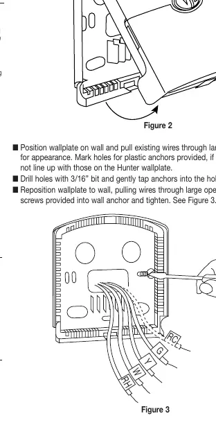
- Wiring: Match wires to the appropriate terminals (Rh, Rc, G, Y, W). If your system has separate Rh and Rc wires (5-wire system), remove the jumper wire between Rh and Rc. For 2, 3, or 4-wire systems, leave the jumper in place.
- Mounting: Remove the wallplate from the thermostat by pressing the release tab. Position the wallplate, level it, and secure it to the wall using the provided anchors and screws.
- Finalizing: Push excess wire back into the wall hole to prevent interference. Snap the thermostat body onto the wallplate. Insert two AA alkaline batteries.
Operation
Setting Day and Time: Press the DAY/TIME key to enter setting mode. Use the Up/Down keys to adjust the hour, minute, and day. Press DAY/TIME again to confirm.
Programming: The thermostat comes with pre-programmed settings. To customize, press the PROGRAM key. Use the Up/Down keys to set the time and temperature for each of the 4 programs per day. Repeat for all days of the week.
Manual Override: Press and hold the HOLD/RET key for 1 second to enter manual override. You can adjust the temperature temporarily, which will be cancelled at the next program change. For a permanent hold (vacation), press the HOLD/RET key once to lock the current temperature.
Settings and Maintenance
Selector Switches: Located on the circuit board, the HG/HE switch must be set correctly. Use 'HG' for gas and oil systems, and 'HE' for electric systems with a fan relay. The F/C switch allows toggling between Fahrenheit and Celsius.
Span Setting: To adjust cycle frequency, press and hold both Up and Down keys for 3 seconds. Adjust the span (1-3) to change how often the system cycles. A higher span increases cycle time.
Battery Replacement: When the low battery indicator flashes, replace the batteries immediately. The thermostat retains settings for approximately 1 minute during battery changes.
Troubleshooting
If the thermostat is not functioning correctly, try the following:
- No Display: Check battery connections or replace batteries. Press the Reset button.
- Heating/Cooling not turning on: Ensure the system switch is in the correct position (HEAT or COOL). Wait up to 4 minutes for the compressor protection delay to expire. Check circuit breakers.
- Err on Display: Replace batteries and press the Reset button.
- Scrambled Display: If the unit is new, remove the clear Mylar sticker from the display. Otherwise, replace batteries.
Practical help
Common problems
No display on the screen
Check battery connections, replace with fresh AA alkaline batteries, or press the Reset button with a paper clip.
Heating or cooling does not turn on
Verify the system switch is set to HEAT or COOL. Wait 4 minutes for the compressor protection delay. Check circuit breakers and ensure the furnace blower door is closed.
Display shows 'Err'
Replace batteries with new ones and press the Reset button. Reprogram the thermostat.
Program does not change at desired setting
Verify the time is set to AM/PM correctly, ensure the thermostat is not in Permanent HOLD mode, and check the day setting.
Before use
- Turn off power to the furnace at the main panel.
- Label all existing wires before disconnecting the old thermostat.
- Ensure you have two AA alkaline batteries.
- Verify system compatibility (not for heat pumps or 110/220V baseboard heat).
- Set the HG/HE switch on the circuit board (HG for gas/oil, HE for electric).
Specs in practice
- Compressor Protection
- A 3.5-minute delay after shutting off cooling to prevent compressor damage.
- HG/HE Switch
- Configures the thermostat for the heating system type. HG for gas/oil, HE for electric.
Images and diagrams
- Wiring Diagrams: Shows specific connections for 2, 3, 4, and 5-wire systems, including jumper wire placement.
- Figure 1: Illustrates the components of the thermostat and wallplate.
- Figure 7: Shows the location of the HG/HE and F/C selector switches on the circuit board.
Model compatibility
- Not compatible with multi-stage heat pumps.
- Not compatible with 110/220V baseboard electric heating systems.
- Designed for gas, oil, and electric furnace systems.

Manual page author
Emily Carter
User documentation editor
Prepares concise manual descriptions and highlights the most useful setup, operation, and maintenance information for readers.