HVAC / Thermostats & Controls
User Manual for GENERAL Life Mitra 110S Digital Room Thermostat
Quick guide for the GENERAL Life Mitra 110S Digital Room Thermostat. Learn about installation, wiring, TPI algorithm operation, battery replacement, and troubleshooting.
Table of contents
Manual images
Click an image to enlargeQuick guide from the manual
The GENERAL Life Mitra 110S is a wired digital room thermostat utilizing TPI (Time Proportional Integral) technology. Key points for users:
- TPI Learning Process: The device learns your home's temperature patterns. This process takes 7 days and restarts if the device is de-energized (battery change) or moved.
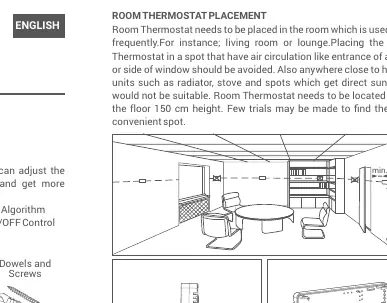
- Placement: Install in a frequently used room (e.g., living room) at a height of 150 cm. Avoid drafts, direct sunlight, and proximity to heating units.
- Compatibility: Compatible with heating units that have on-off connections.
- Professional Installation: Wiring must be performed by qualified personnel.
Product Description
The Mitra 110S allows precise temperature measurement and control. It features an adjustment knob for setting the desired temperature and an LED indicator to show the relay status.
Installation and Placement
Proper placement is critical for accurate temperature control. Avoid placing the thermostat near windows, doors, or heat sources like radiators. Ensure there is air circulation around the unit. The recommended installation height is 150 cm above the floor.
Wiring
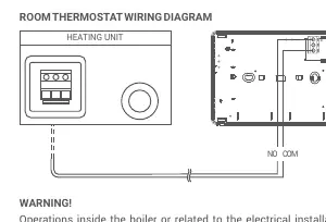
Warning: Operations involving the boiler or electrical installation must be carried out by persons with professional competence. Use a 2x0.75 mm cable for the connection. Connect the cable to the COM and NO inputs of the terminal inside the Wall Hanger of the Room Thermostat, and the other end to the room thermostat connection terminals on your heating unit.
Battery Placement
The device uses 2 x AAA alkaline batteries. To replace them:
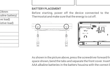
- Power off the device and ensure energy is cut off.
- Press the screwdriver into the designated space to bend the tabs and separate the front cover.
- Insert new batteries ensuring correct polarity.
- Align the front part to the back and squeeze to close.
Note: Remove batteries if the product will not be used for more than 15 days to prevent damage.
Operation and TPI Logic
The TPI algorithm predicts when the temperature will rise above or below the set point and cycles the heating unit accordingly to maintain a stable temperature. The LED indicator provides status updates:
- Blinks once: The relay contact opens, and the heating unit stops.
- Blinks twice: The relay contact closes, and the heating unit starts.
Technical Data
- Dimensions: 85mm / 125mm / 24mm
- Operating Current: 3V DC (2 x AAA alkaline battery)
- Relay NO Switching Current: 2A/30VDC (Resistive load) or 0.5A/125VAC (Resistive load)
- Temperature Measurement Accuracy: 0.1°C
- Operating Temperature Range: 5°C – 35°C
Practical help
Common problems
Heating unit does not start or stop correctly
Verify that the wiring to the COM and NO terminals is secure and correctly connected to the heating unit's thermostat terminals.
Thermostat seems inaccurate or slow to react
The TPI algorithm requires a 7-day learning period. If the device was recently moved or batteries were changed, allow 7 days for the learning process to complete.
LED blinks once
This indicates the relay contact has opened and the heating unit has stopped.
LED blinks twice
This indicates the relay contact has closed and the heating unit has started.
Before use
- Ensure your heating unit supports on-off connections.
- Power off the heating unit before starting installation.
- Select a location 150 cm above the floor in a frequently used room.
- Avoid locations with direct sunlight, drafts, or near radiators.
- Have 2 new AAA alkaline batteries ready.
- Ensure a 2x0.75 mm cable is available for wiring.
Specs in practice
- TPI Algorithm
- Advanced AI that learns your home's thermal characteristics to minimize energy consumption and temperature fluctuations.
- Relay NO Switching Current
- The maximum electrical load the thermostat can switch (2A/30VDC or 0.5A/125VAC resistive).
- Operating Temperature Range
- The range of temperatures the thermostat can regulate (5°C to 35°C).
Images and diagrams
- Wiring Diagram: Shows the connection path between the heating unit and the thermostat using COM and NO terminals.
- Placement Diagram: Illustrates the ideal mounting height (150 cm) and clearance (min 20 cm) from obstacles.
Model compatibility
- Compatible with any heating unit that features on-off connections.

Manual page author
Emily Carter
User documentation editor
Prepares concise manual descriptions and highlights the most useful setup, operation, and maintenance information for readers.