HVAC / Refrigeration Controllers
User Manual for AKO-145601 Controller
Quick guide for the AKO-145601 controller. Includes wiring diagrams, initial configuration steps, parameter settings, and troubleshooting error messages.
Table of contents
Manual images
Click an image to enlargeQuick Start Guide
To begin using the AKO-145601 controller, follow these steps:
- Connect the controller according to the wiring diagram.
- Configure the rFt (refrigerant gas), EM (expansion valve model), and SH (overheating set point) parameters.
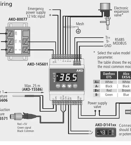
Wiring
The controller requires a 24V power supply. Ensure the probe and its cable are installed in a conduit separate from power supply or control cables. Probes 1 and 2 should be installed as close as possible to the evaporator output. The device includes an RS485 port for MODBUS communication.
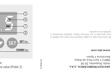
Operation and Keypad
The keypad allows for navigation and configuration:
- PRG key: Press for 5 seconds to access the programming menu. Press twice to restart regulation after an alarm.
- SET key: Used to accept changes. Press for 5 seconds to exit the programming menu.
- UP/DOWN keys: Used to scroll through levels or change parameter values.
Initial Configuration
Before start-up, configure the following parameters:
- rFt: Select the refrigerant gas type (e.g., R-22, R-134A, R-404A, etc.).
- EM: Select the expansion valve model (e.g., Danfoss ETS, Alco EX, Sporlan SEI, Carel E2V).
- SH: Configure the overheating set point.
Parameter Adjustment
To access the programming menu, press the PRG key for 5 seconds until "PwD" is displayed. Enter the password (default is 5) and press SET. The parameters are divided into three groups:
- Group 1: Includes overheating set point, proportional gain, integral time, derivative time, and various alarm settings (overheating, pressure, freeze).
- Group 2: Includes pressure and temperature units, expansion valve model selection, and valve speed settings.
- Group 3: Includes password settings, refrigerant gas type, probe calibration, and communication settings.
Error Messages
The controller displays specific codes for faults:
- PS: Problem in the pressure sensor.
- TSD: Probe 1 not connected.
- TsC: Crossed temperature probe.
- MOP: Maximum Operation Pressure alarm.
- LOP: Lower Operation Pressure alarm.
- FRA: Frost detection alarm.
- STP: Regulation stopped by external thermostat.
- CAL: Expansion valve initialization.
- CLE: Valve closing due to power supply fault.
Manufacturer information
AKO Group
Practical help
Common problems
Probe 1 not connected (TSD error)
Check the probe connection and wiring.
Pressure sensor problem (PS error)
Check the sensor wiring and connection.
Regulation stopped (STP message)
Check the external thermostat input (ON/OFF).
Before use
- Ensure power supply is 24V AC/DC.
- Verify probe installation (as close as possible to evaporator output).
- Check wiring section for correct terminal connections.
- Configure refrigerant gas type (rFt parameter).
- Select expansion valve model (EM parameter).
Specs in practice
- Power supply
- 24V AC/DC, 50/60 Hz.
- Protection degree
- IP2X.
- Working temperature
- -10 to 50 ºC.
Images and diagrams
- Wiring diagram shows connections for probes, RS485, and power supply.
- Keypad diagram explains PRG, SET, UP, and DOWN buttons.
Model compatibility
- Compatible with various refrigerant gases (R-22, R-134A, R-404A, etc.).
- Supports multiple expansion valve models (Danfoss, Alco, Sporlan, Carel).

Manual page author
Michael Turner
Technical manual editor
Reviews PDF manuals for structure, safety notes, and practical product details so readers can find the right information quickly.