HVAC / Heat Pumps
Installation and Operating Instruction for Dimplex LA 0712BW / LA 0712BWC Heat Pump
Quick guide for the Dimplex LA 0712BW and LA 0712BWC air-to-water heat pumps. Includes installation, commissioning, maintenance, and technical specifications.
Table of contents
Manual images
Click an image to enlargeImportant information from the manual
This document provides essential instructions for the installation, operation, and maintenance of the Dimplex LA 0712BW and LA 0712BWC air-to-water heat pumps. Professional installation is required. The heat pump must be operated with the included Hydro-Tower and heat pump manager. Ensure the system is protected against frost and that the minimum heating water flow rate is maintained at all times to prevent system blockage.
Intended use
The air-to-water heat pump is designed exclusively for heating or cooling heating water in domestic environments. It is suitable for mono-energetic and bivalent operation. The device is not suitable for operation with a frequency converter or for use at altitudes above 2000 meters.
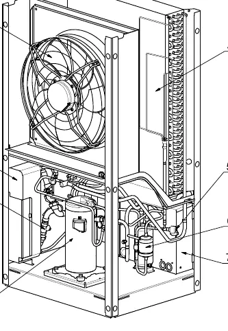
Scope of supply
The basic device includes the heat pump unit with a metal casing, switch box, and integrated heat pump manager. The refrigeration circuit is hermetically sealed and contains R410A refrigerant.
Transport
Transport the heat pump using a pallet. Do not tilt the unit by more than 45 degrees in any direction. Remove the four transport bolts connecting the unit to the pallet before installation. After transport, remove the transport fastening from both sides of the base before commissioning.
Installation
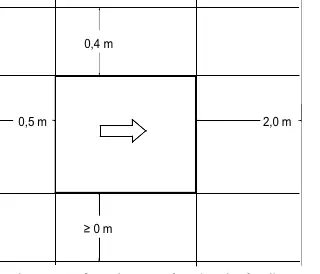
Install the device on a permanently smooth, even, and horizontal surface. Ensure the frame is in direct contact with the ground for soundproofing. Maintain the specified clearances to solid walls (0.5m, 2.0m, 0.4m) to allow for maintenance. Do not restrict the air intake or outlet areas. Installation in hollows or inner courtyards is prohibited.
Assembly
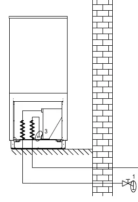
Connections required include the flow and return of the heating system, condensate drain, control cable to the heat pump manager, and power supply. Use a spanner to grip transitions when connecting the heating system. Flush the heating system before connection to remove impurities.
Commissioning
Commissioning must be performed by an authorized service technician. Ensure all valves are open, air paths are clear, and the fan rotates in the correct direction. The heat pump manager is used to start the commissioning program. If heating water temperatures are below 7°C, the water in the buffer tank must be heated to at least 18°C using a second heat generator.
Cleaning and maintenance
Keep the exterior clean with a damp cloth and mild cleaner; do not use abrasive or acidic agents. Before opening the device for cleaning, ensure all circuits are disconnected from the power supply and wait at least 5 minutes for electrical charges to dissipate. Clean the evaporator, fan, and condensate drain of debris (leaves, twigs) before each heating period.
Troubleshooting
Faults are indicated on the heat pump manager display. Consult the 'Faults and troubleshooting' section in the heat pump manager's operating instructions. If the fault cannot be resolved, contact an authorized service technician.
Technical data
The heat pump operates with R410A refrigerant. It features a nominal heating capacity of 7 kW (at A7/W35). The system requires a minimum heating water flow of 1.4 m³/h. Detailed electrical and performance data are provided in the device information tables.
Manufacturer information
Dimplex
Practical help
Common problems
Heat pump blocked
Ensure the minimum heating water flow rate is maintained in all operating states.
Fault indicated on display
Consult the 'Faults and troubleshooting' section in the heat pump manager operating instructions.
Ice formation on air grids
Remove ice and snow from the vicinity of the air intake and outlet grids to ensure minimum airflow.
Before use
- Ensure all connections are installed as described in the manual.
- Verify all valves in the heating circuit are open.
- Check that air intake and outlet paths are clear.
- Confirm fan rotation matches the arrow direction.
- Ensure condensate drain is functional.
- Verify settings on the heat pump manager.
Specs in practice
- Operating limits (Heating)
- Ambient air temperature range from -22°C to +35°C.
- Minimum heating water flow
- Required flow rate (1.4 m³/h) to prevent the heat pump from blocking.
- Max. operating pressure
- Maximum pressure allowed in the heat sink (3.0 bar).
Images and diagrams
- The manual includes hydraulic integration diagrams for mono-energetic systems with one or three heating circuits.
- Dimension drawings show the required clearances for installation (0.5m, 2.0m, 0.4m).
- Characteristic curves for heating and cooling operations are provided in the appendix.
Model compatibility
- Requires the included Hydro-Tower with heat pump manager for operation.
- Not suitable for operation with a frequency converter.
- Not intended for use at altitudes above 2000 meters.

Manual page author
Michael Turner
Technical manual editor
Reviews PDF manuals for structure, safety notes, and practical product details so readers can find the right information quickly.