HVAC / Thermostats & Controls
Dimplex WPM Touch Heat Pump Manager Installation Manual
Installation guide for the Dimplex WPM Touch heat pump manager. Includes mounting instructions, electrical wiring diagrams, sensor installation, and technical specifications.
Table of contents
Manual images
Click an image to enlargeQuick guide from the manual
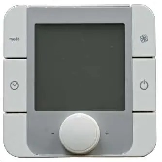
The WPM Touch is a heat pump manager designed for wall mounting. It must be installed in a dry room with an ambient temperature between 0°C and 35°C. Ensure no condensation forms on the device. The unit requires a continuous power supply to maintain frost protection functions.
Mounting the heat pump manager
The controller is attached to the wall using the 3 screws and dowels (6 mm) included in the scope of supply. Follow these steps for installation:
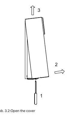
- Open the controller cover.
- Mount the dowels for the upper fastening eyelet at operator level.
- Screw the screw into the dowel so the controller can be hung.
- Mount the controller by the upper fastening eyelet.
- Mark the position of the side drill-holes.
- Unhook the controller, mount the side dowels, and remount the controller to tighten all screws.
Temperature sensors
The system uses NTC-2 and NTC-10 sensors. The outside temperature sensor (R1) is NTC-2. Other sensors (heating circuit, domestic hot water, demand, renewable cylinder) are NTC-10. Sensor cables can be extended up to 40m (or 50m with 2 x 0.75 mm cables) and should not be installed next to power cables.
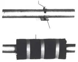
Strap-on sensor installation:
- Remove paint, rust, and scale from the heating pipe.
- Coat the cleaned surface with heat transfer compound.
- Attach the sensor with a hose clip and thermally insulate.
Electrical installation
The electrical supply cable (L/N/PE~230 V, 50 Hz) must have a continuous voltage and should be tapped upstream from the utility company blocking contactor. An all-pole disconnecting device with a contact gap of at least 3 mm must be installed.
Key wiring requirements:
- Utility blocking contactor (K22): Connect the NO contact (13/14) to pin (1) (=DI1) of function block 0.
- Immersion heater (E10): Controlled via pin (7) (=NO3) of function block 0.
- Circulating pumps: Connect the heat circulating pump (M13) to pin (5) and (8) of function block 0.
- Caution: Extra-low voltage is present at adapter boards -N1/SL, -N1/ML, -N17/LV. Connecting line voltage to these terminals will destroy the manager.
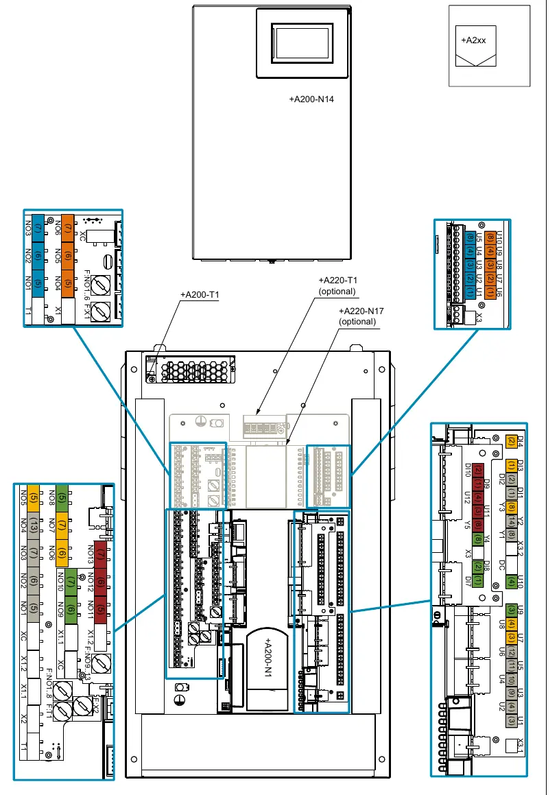
Functions and pin assignment
The WPM Touch has a fixed pin assignment for the "General/1st unmixed circuit" on the grey function block. Additional functions can be assigned to three flexible function blocks (yellow, green, red). If more are needed, two further blocks (orange, blue) can be added via expansion accessories. During commissioning via the touch display, the function and color assignment are queried and set.
Special accessories
The manager supports the RTM Econ room temperature controller for cooling regulation. It can also be connected to a building management system via EIB, KNX, Ethernet, Modbus TCP, or Modbus RTU.
Manufacturer information
Dimplex
Practical help
Common problems
Sensor cables are too long or installed incorrectly
Maximum length is 40m (or 50m with 2x0.75mm cables). Do not install sensor cables next to power cables.
High starting current for circulating pumps
If using electronically regulated circulating pumps with high starting currents, install a coupling relay to protect the manager.
Wiring error destroying the device
Never connect line voltage to extra-low voltage terminals (adapter boards -N1/SL, -N1/ML, -N17/LV, or specific pins on J9, J14, J29, J6). This will destroy the manager.
Before use
- Ensure installation in a dry room (0°C to 35°C).
- Verify no condensation forms on the device.
- Ensure an all-pole disconnecting device is installed in the power supply.
- Check that sensor cables are not routed alongside power cables.
- Verify the utility company blocking contactor is dimensioned correctly.
Specs in practice
- Line voltage
- 230 V AC 50 Hz
- Degree of protection
- IP 20
- Operating temperature
- 0°C to +35°C
- Switching capacity
- min. 2 A (2 A) cos (φ) = 0.6 LRA = 12 A at 230 V
Images and diagrams
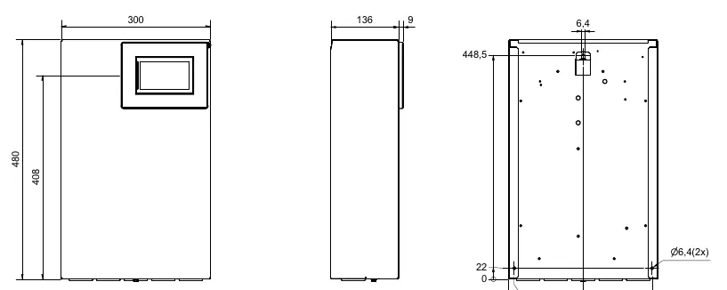
- Wall mounting dimensions are provided for precise positioning of the unit.
- Pin assignment tables define connections for fixed and flexible function blocks.
- Strap-on sensor installation requires cleaning the pipe and using heat transfer compound.
Model compatibility
- Compatible with RTM Econ room temperature controller.
- Supports building management systems via EIB, KNX, Ethernet, Modbus TCP, or Modbus RTU.

Manual page author
Michael Turner
Technical manual editor
Reviews PDF manuals for structure, safety notes, and practical product details so readers can find the right information quickly.