HVAC / Heat Pumps
Installation Guide for Dimplex M Flex Heat Pump
Quick installation and wiring guide for Dimplex M Flex heat pumps. Includes electrical and hydraulic layout diagrams, sensor connections, and configuration settings for heating, hot water, and cooling circuits.
Table of contents
Manual images
Click an image to enlargeQuick Guide
This document provides technical installation and wiring layouts for the Dimplex M Flex heat pump series. It is intended for professional installers to configure electrical and hydraulic connections. The guide includes specific wiring diagrams for various system functions, including domestic hot water, heating circuits, and cooling.
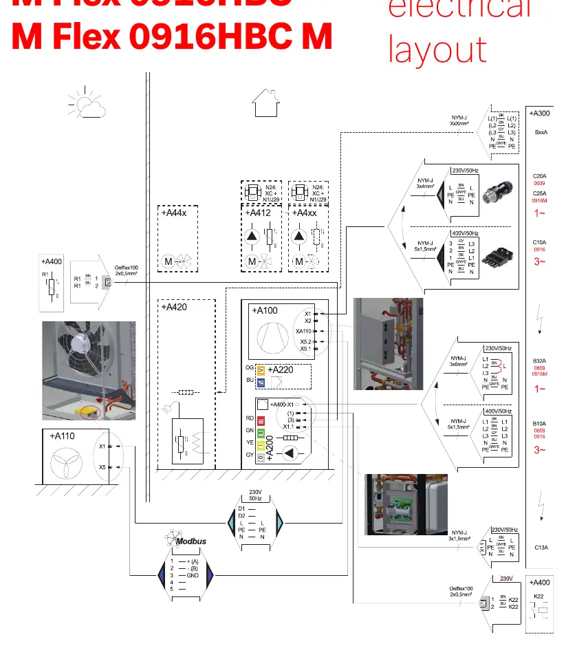
Electrical Layout
The electrical layout provides an overview of the power supply connections and main component integration. It details the required cable types (e.g., NYM-J, Oelflex 100) and cross-sections for different power requirements (230V/50Hz or 400V/50Hz).
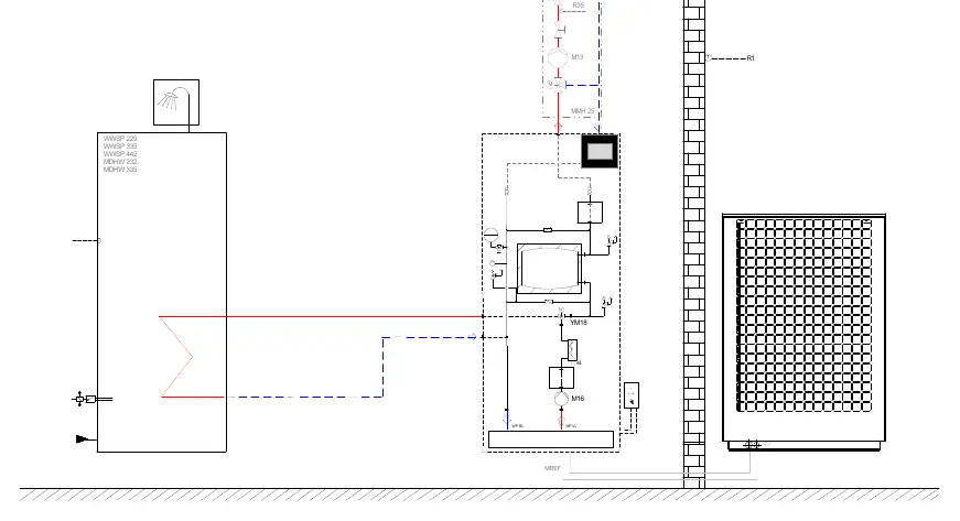
Hydraulic Layout
The hydraulic layout illustrates the water circuit connections, including the integration of the heat pump with domestic hot water storage tanks (e.g., WWSP, MDHW series) and circulation pumps. It highlights the flow and return paths (WP VL, WP RL) and the positioning of sensors and valves.
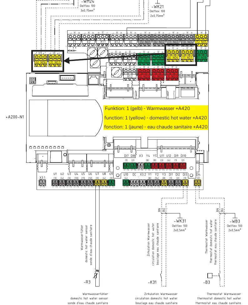
Wiring Connections
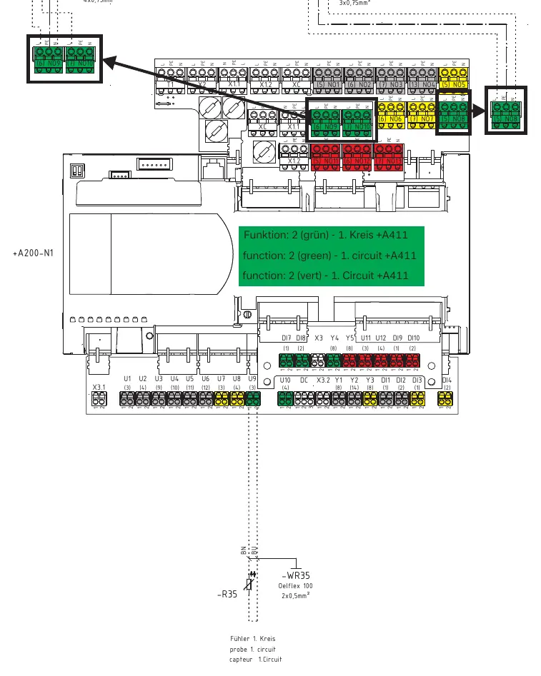
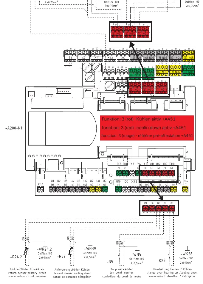
The wiring section provides detailed terminal block diagrams for the control unit (+A200-N1). Connections are categorized by function, using specific color-coded labels to identify the required configuration:
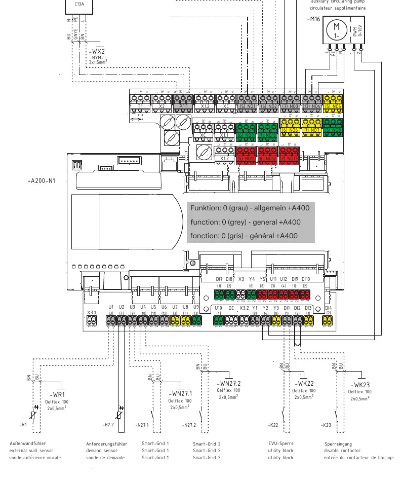
- Function 0 (Grey) - General (+A400): Standard system connections.
- Function 1 (Yellow) - Domestic Hot Water (+A420): Connections for hot water sensors, circulation pumps, and reversing valves.
- Function 2 (Green) - 1st Circuit (+A411): Connections for mixer circuits and circulating pumps.
- Function 3 (Red) - Cooling (+A451): Connections for cooling demand sensors, dew point monitors, and change-over valves.
Manufacturer information
Dimplex
Practical help
Common problems
Incorrect wiring configuration
Ensure the wiring matches the specific function color code (Grey: General, Yellow: Hot Water, Green: 1st Circuit, Red: Cooling) as shown in the terminal diagrams.
Sensor connection errors
Verify that sensors (e.g., external wall sensor, demand sensor) are connected to the correct terminal blocks (U1-U9, DI1-DI10) as specified in the wiring diagrams.
Before use
- Verify the specific model (0609HBC or 0916HBC) matches the installation requirements.
- Ensure power supply is disconnected before performing any wiring.
- Check that all cable types and cross-sections (e.g., 3x1.5mm², 2x0.5mm²) meet the specifications shown in the diagrams.
- Identify the required system functions (Heating, Hot Water, Cooling) to apply the correct wiring configuration.
- Confirm all sensors and actuators are correctly identified and connected to the control unit (+A200-N1).
Specs in practice
- 230V/50Hz / 400V/50Hz
- Power supply voltage and frequency requirements for different system components.
Images and diagrams
- Electrical layout: Overview of power supply and main component connections.
- Hydraulic layout: Integration of heat pump with water circuits and storage tanks.
- Plug-in diagrams: Detailed terminal block connections for specific system functions.
Model compatibility
- Applicable to M Flex 0609HBC and 0916HBC series.
- Supports integration with various domestic hot water tanks (WWSP, MDHW series).

Manual page author
Michael Turner
Technical manual editor
Reviews PDF manuals for structure, safety notes, and practical product details so readers can find the right information quickly.