HVAC / Heat Pumps
Installation Guide for Dimplex LIA 0608BWCF M and LIA 0911BWCF M Heat Pump
Quick installation and electrical wiring guide for Dimplex LIA 0608BWCF M and LIA 0911BWCF M split heat pumps. Includes detailed electrical layouts, hydraulic diagrams, and connection instructions for sensors, pumps, and smart grid...
Table of contents
Manual images
Click an image to enlargeQuick guide from the manual
This document provides essential electrical and hydraulic installation diagrams for the Dimplex LIA 0608BWCF M and LIA 0911BWCF M split heat pump systems. It outlines the necessary wiring connections between the outdoor unit (+A100), the Hydrotower (+A200), and the electrical distribution system (+A300), as well as specific configurations for domestic hot water and cooling circuits.
Electrical Layout
The electrical installation requires careful connection between the main components. The system utilizes specific cable types and fuse ratings:
- Power Supply: Ensure correct wiring for the 3-phase system.
- Fuses: The system requires specific protection, including B20A, C13A, and C20A fuses depending on the circuit.
- Cabling: Use specified cables such as NYM-J (e.g., 5x4mm², 3x4mm², 3x1.5mm²) for power and Oelflex 100 (e.g., 2x0.5mm²) for control signals.
- Connections: The diagram details the interface between the Hydrotower (+A200) and the electrical distribution system (+A300), including the utility block contactor (-K22).
Hydraulic System
The hydraulic layout provides an overview of the water circuit, including the heat pump unit (R1), the Hydrotower (N1), and associated sensors (E9, E10.1, R2) and pumps (M16).
Plug-in Connections
The manual details the terminal connections on the Hydrotower controller (+A200-N1) for various system extensions:
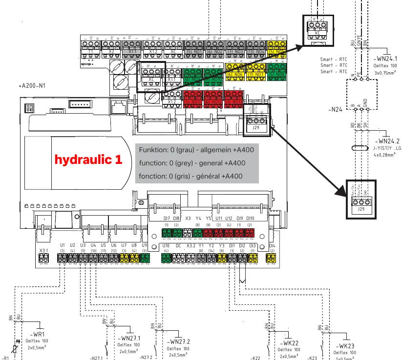
- Sensors: Connection points for external wall sensors (-R1).
- Smart-Grid: Terminals for Smart-Grid 1 and Smart-Grid 2 integration.
- Fault Indicators: Connection for remote fault indicators (-H5).
- Utility Block: Terminals for utility block (EVU-Sperre) and disable contactor inputs.
System Functions
The controller supports specific functional configurations via terminal wiring:
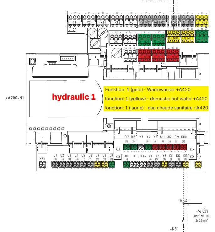

- Domestic Hot Water: Connection for the circulation pump (-M24) using function 1 (yellow).
- Cooling Circuit: Connection for cooling down active/indoor cooling circuit (+A150) using function 3 (red).
Manufacturer information
Dimplex
Practical help
Common problems
Incorrect system function
Verify that the wiring for the specific function (e.g., Hot Water or Cooling) is connected to the correct terminal block as indicated in the wiring diagrams.
Communication error between units
Check the FBUS 1 connection (J9) between the outdoor unit and the Hydrotower, ensuring the 4x0.28mm² cable is securely connected.
Before use
- Ensure the power supply is disconnected before performing any wiring.
- Verify that all fuse ratings (B20A, C13A, C20A) match the requirements for the specific circuit.
- Confirm the use of correct cable types (NYM-J for power, Oelflex 100 for control).
- Check that all terminal connections are tight and secure.
- Verify the 3-phase power supply configuration.
Specs in practice
- Oelflex 100 2x0.5mm²
- Control cable for sensors and low-voltage signals.
- B20A / C13A / C20A
- Required fuse/circuit breaker ratings for different system components.
Images and diagrams
- The electrical layout shows the interconnection between the outdoor unit (+A100), Hydrotower (+A200), and distribution board (+A300).
- Plug-in diagrams illustrate the specific terminal blocks on the controller (+A200-N1) for sensors and external inputs.
Model compatibility
- Designed for 3-phase electrical systems.
- Supports specific external functions like Smart-Grid, domestic hot water circulation, and indoor cooling.

Manual page author
Emily Carter
User documentation editor
Prepares concise manual descriptions and highlights the most useful setup, operation, and maintenance information for readers.