Electronics / Security Systems
Installation Guide for DMP 1100D Series Wireless Receiver
Quick installation and setup guide for the DMP 1100D Series Wireless Receiver. Includes wiring diagrams, panel programming steps, LED status indicators, and compatibility specifications.
Table of contents
Quick guide from the manual
The 1100D Series Wireless Receiver is designed to provide wireless zones for DMP XT30/XT50 panels. Key installation steps include programming the panel with a House Code, selecting a location using an LED survey, and wiring the receiver to the panel's keypad bus.
Description and Compatibility
The 1100D provides two-way, supervised communication using 900 MHz frequency hopping spread spectrum technology. The 1100DE model features 128-bit AES encryption.
- Compatible Panels: XT30 Series and XT50 Series (firmware version 102 or higher).
- Encryption Requirements: Panel version 183 or higher.
- Translator Requirements: 1100T Translator requires receiver firmware version 207/301 or higher.
Programming the Panel
- Reset the panel.
- Access the PROGRAMMER menu by entering 6653 (PROG) at a keypad.
- In SYSTEM OPTIONS, program a HOUSE CODE between 1 and 50.
- For XT50 panels, select NO at the BUILT IN 1100 WIRELESS prompt.
- For 1100DE models, select ALL or BOTH at the 1100 ENCRYPTION prompt.
- Set the passphrase if required (8-character hexadecimal string).
- Press CMD until STOP displays, then save programming.
Selecting a Location
Perform an LED survey to ensure clear communication before permanent mounting:
- Remove the receiver cover and hold the transmitter in the desired location.
- Press the tamper switch to send data to the panel.
- Confirmed: The LED blinks immediately on and off for each press/release.
- Faulty: The LED remains on for 8 seconds or flashes multiple times. Relocate the receiver until communication is confirmed.
Wiring and Mounting
Do not use shielded or twisted pair wire for data circuits. Use 18 or 22-gauge unshielded wire.
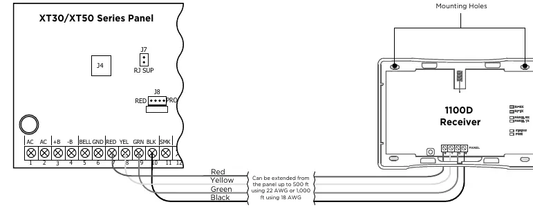
- Connect the red, yellow, green, and black wires to the PANEL terminal on the 1100D.
- Connect the other end of the wires to terminals 7, 8, 9, and 10 on the panel.
- Secure the 1100D to the wall using the included #6 screws.
- Snap the cover back onto the base.
LED Operation
The six labeled LEDs on the PCB indicate receiver status:
- RF RX: Flashing yellow indicates data received from a transmitter.
- RF TX: Flashing green indicates data sent to a transmitter.
- PANEL RX: Flashing yellow indicates data received from a panel.
- PANEL TX: Flashing green indicates data sent to the panel.
- STATUS: Solid red indicates memory is being uploaded.
- PWR: Solid green indicates power to the receiver.
Specifications
- Operating Voltage: 12 VDC Nominal.
- Current Draw: 25 mA (average), 35 mA (peak).
- Frequency Range: 905-924 MHz.
- Housing Dimensions: 5.50" W x 3.75" L x 1.00" H.
- Housing Material: Flame Retardant ABS.
Practical help
Common problems
Communication faulty during LED survey
The LED remains on for 8 seconds or flashes multiple times. Relocate the receiver until the LED confirms clear communication.
Voltage drop issues
If voltage at any device is less than required, add an auxiliary power supply at the end of the circuit.
Data transmission interference
Do not use twisted pair or shielded wire for LX-Bus and Keypad Bus data circuits.
Before use
- Verify panel firmware version (XT30/XT50).
- Ensure panel firmware is 183+ for encryption support.
- Program a House Code between 1 and 50.
- Use 18 or 22-gauge unshielded wire.
- Do not exceed 500 feet with 22-gauge wire or 1,000 feet with 18-gauge wire.
Specs in practice
- Operating Voltage
- 12 VDC Nominal required for operation.
- Current Draw
- 25 mA average, 35 mA peak power consumption.
- Frequency Range
- 905-924 MHz for wireless communication.
Images and diagrams
- Figure 1 shows the 1100D Wireless Receiver layout.
- Figure 2 illustrates the wiring connections between the panel terminals (7, 8, 9, 10) and the receiver.
Model compatibility
- Compatible with XT30 and XT50 Series panels.
- 1100T Translator requires receiver firmware version 207/301 or higher.

Manual page author
Michael Turner
Technical manual editor
Reviews PDF manuals for structure, safety notes, and practical product details so readers can find the right information quickly.