Electronics / Security Systems
Installation Guide for DMP 1142HD Wireless Two-Button Transmitter
Quick installation and setup guide for the DMP 1142HD Wireless Two-Button Transmitter. Includes programming steps, battery installation, mounting instructions, and system testing procedures.
Table of contents
Manual images
Click an image to enlargeQuick guide from the manual
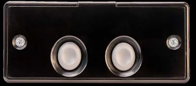
The DMP 1142HD is a wireless two-button holdup transmitter designed for mounting under a counter or on a wall. It features a tamper switch for security and optional 128-bit AES encryption. This guide covers the programming, installation, and testing of the device.
Programming the Panel
Before installing the battery, program the zone in the control panel:
- At a keypad, enter 6653 (PROG) to access the Programmer Menu.
- If using encryption, navigate to SYSTEM OPTIONS, set 1100 ENCRYPTION to ALL or BOTH, and set the passphrase.
- In ZONE INFORMATION, enter the wireless ZONE NO and ZONE NAME.
- Select PN (panic) as the ZONE TYPE.
- Set WIRELESS to YES.
- Enter the eight-digit SERIAL# and the SUPRVSN TIME.
- At LED OPER, select YES to enable the LED indicator during panic signals.
Battery Installation
Use a 3.0V lithium CR123A battery. It is recommended to use Energizer, Panasonic, or Tekcell brands for UL installations.
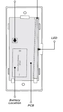
- Open the 1142HD housing.
- Observe the correct polarity and place the battery into the holder.
- Press the battery into place.
Selecting a Location
Use the Survey LED to confirm communication before final mounting:
- Hold the transmitter in the desired location.
- Press the tamper switch.
- Confirmed: The LED blinks immediately on and off for each press/release. Repeat to confirm five consecutive blinks.
- Faulty: The LED remains on for about 8 seconds or flashes rapidly. Relocate the transmitter or receiver until communication is clear.
Mounting the Transmitter
The unit is equipped with case and wall tamper switches.
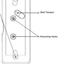
- Set aside the top housing (containing the PCB and battery).
- Place the base housing in the desired location with the LED cut-out facing you.
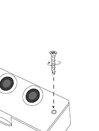
- Secure the base using the two supplied Phillips mounting screws. Use an additional screw in the tamper hole to mount it against the wall.
- Align the top housing with the base, ensuring the tamper switch is aligned, and secure the housing using the included screws.
Testing
After installation, perform a Wireless Check-in Test:
- At the keypad, enter 8144 (WALK) and select WLS.
- If the transmitter fails to check in, check for interference from metal objects or electronic equipment.
Maintenance and Reset
If a LOBAT message appears on the keypad, replace the battery. After replacement, perform a sensor reset:
- On a Thinline keypad, press and hold 2 for two seconds.
- On a touchscreen keypad, press RESET.
- Enter your user code if required. The keypad will display SENSORS OFF followed by SENSORS ON.
Specifications and Compatibility
Compatibility: 1100 Series Wireless Receivers, XTL, XT, and XR Series Control Panels. Note: Encryption requires Version 183+ for XT/XR panels and Version 300+ for Wireless Receivers.
Contact: For further assistance, visit DMP.com or call 800.641.4282.
Official resources from the manual
Practical help
Common problems
Communication faulty (LED remains on for 8 seconds or flashes rapidly)
Relocate the transmitter or receiver until the LED confirms clear communication.
Transmitter fails to check in during test
Ensure it is wired properly and check for sources of interference such as metal objects and electronic equipment.
LOBAT message on keypad
Replace the battery and perform a sensor reset (hold '2' or press RESET on keypad).
Before use
- Verify compatibility with 1100 Series Wireless Receivers or XTL/XT/XR Series Control Panels.
- Ensure panel firmware version is 183+ (XT/XR) or 300+ (Wireless Receivers) if using encryption.
- Have a 3.0V Lithium CR123A battery ready.
- Program the zone in the panel before installing the battery.
Specs in practice
- Battery Type
- 3.0V Lithium CR123A
- Frequency Range
- 905-924 MHz
- Life Expectancy
- 5 years (normal operation)
Images and diagrams
- Figure 1: PCB Components showing tamper switch, antenna, and battery location.
- Figure 2: Base housing installation showing mounting holes and wall tamper.
- Figure 3: Top housing installation showing screw assembly.
Model compatibility
- Requires 1100 Series Wireless Receivers.
- Compatible with XTL, XT, and XR Series Control Panels.

Manual page author
Emily Carter
User documentation editor
Prepares concise manual descriptions and highlights the most useful setup, operation, and maintenance information for readers.