Electronics / Security Systems
Installation Guide for DMP 1100XH Series Wireless Receiver
Comprehensive installation and setup guide for the DMP 1100XH Series High Power Wireless Receiver. Includes wiring diagrams, panel programming steps, LED status indicators, and mounting instructions.
Table of contents
Manual images
Click an image to enlargeQuick guide from the manual
The 1100XH Series High Power Wireless Receiver is designed to provide wireless zones for XR150 and XR550 Series panels. This document provides the necessary steps for installation, wiring, and panel programming. Ensure you have the required hardware and panel firmware version before beginning.
Programming the Panel
Before mounting, the panel must be programmed to recognize the receiver.
- Reset the panel.
- Access the PROGRAMMER menu at a keypad by entering 6653 (PROG).
- In SYSTEM OPTIONS, program a HOUSE CODE between 1 and 50.
- For 1100XHE models, select ALL to add encrypted devices or BOTH to allow encrypted and non-encrypted devices at the 1100 ENCRYPTION prompt.
- Set the passphrase if required (default is recommended).
- Press CMD until STOP displays, then save the programming.
Selecting a Location
The receiver should be centrally located between the DMP panel and the transmitters. Use an 1106 Series Universal Wireless Transmitter to perform an LED survey:
- Hold the transmitter in the desired location with the receiver cover removed.
- Press the tamper switch.
- Confirmed: The LED blinks immediately on and off for each press/release.
- Faulty: The LED remains on for 8 seconds or flashes rapidly. Relocate the receiver until communication is confirmed.
Mounting the 1100XH
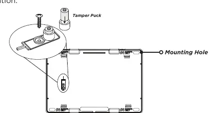
- Remove the cover from the plastic housing.
- Secure the 1100XH to the wall using the included #6 screws.
- Anchor the housing in the wall tamper screw hole using the provided screw.
Wiring the Receiver
The receiver connects to the panel via the XBUS. Do not use shielded or twisted pair wire.
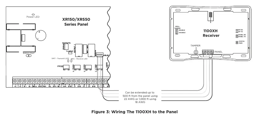
- Connect the red, yellow, green, and black wires to the PANEL terminal on the 1100XH.
- Connect the other end of the wires to the XBUS on the panel.
- Snap the cover back onto the base.
Note: The receiver will not operate if connected to the keypad bus.
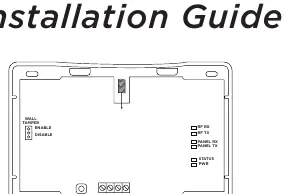
LED Operation
The six LEDs on the PCB indicate system status:
- RF RX: Flashing yellow indicates data received from a transmitter.
- RF TX: Flashing green indicates data sent to a transmitter.
- PANEL RX: Flashing yellow indicates data received from a panel.
- PANEL TX: Flashing green indicates data sent to the panel.
- STATUS: Solid red indicates memory is being uploaded.
- PWR: Solid green indicates power is present.
Specifications
- Operating Voltage: 12 VDC Nominal.
- Current Draw: 75 mA (average), 102 mA (peak).
- Frequency Range: 905-924 MHz.
- Housing Dimensions: 5.5 inches W x 3.75 inches L x 1 inch H.
- Housing Material: Flame Retardant ABS.
Practical help
Common problems
Communication faulty during LED survey
The LED remains on for 8 seconds or flashes rapidly. Relocate the receiver until the LED confirms clear communication.
Receiver not operating
Ensure the receiver is not connected to the keypad bus; it must be connected to the XBUS.
Low voltage at device
If voltage is below the required level, add an auxiliary power supply at the end of the circuit.
Before use
- Verify panel firmware is Version 183 or higher for encryption support.
- Use unshielded 18 or 22-gauge wire for all connections.
- Program a House Code between 1 and 50.
- Perform an LED survey using an 1106 Series transmitter before final mounting.
- Ensure wire length does not exceed 2,500 feet total.
Specs in practice
- Operating Voltage
- 12 VDC Nominal power requirement.
- Frequency Range
- 905-924 MHz frequency hopping spread-spectrum technology.
- Current Draw
- 75 mA average consumption, peaking at 102 mA.
Images and diagrams
- Figure 1: Overview of the 1100XH housing and LED locations.
- Figure 2: Internal view showing mounting holes and the tamper puck location.
- Figure 3: Wiring diagram showing connections between the 1100XH and the panel XBUS.
Model compatibility
- Compatible with XR150 and XR550 Series Panels.
- 1100T Translator requires receiver firmware Version 207/301 or higher.
- Encryption requires panel Version 183 or higher.

Manual page author
Michael Turner
Technical manual editor
Reviews PDF manuals for structure, safety notes, and practical product details so readers can find the right information quickly.