HVAC / Ventilation Systems
Installation Guide for DucoBox Focus
Comprehensive installation and configuration guide for the DucoBox Focus ventilation system. This manual covers mounting, wiring, control valve setup, component pairing, and air flow calibration procedures.
Quick answers from the manual
Quick answer
- The DucoBox Focus is a demand-controlled ventilation unit. Installation involves mounting the unit, connecting power and communication cables, pairing control valves and components via 'Installer mode', and performing an automatic air flow calibration. p. 3, 5, 6, 13
Key actions
- Mounting the unit p. 5
- Wiring connections p. 6
- Pairing components p. 11
- Air calibration p. 13, 14
First start
- Power on p. 14
Problems and fixes
System not working correctly
Restart the DucoBox. Follow the guidelines in '10 essential tips' if the problem recurs.
p. 10Maintenance and reset
- Restoring factory settings p. 12
Technical specifications
| Parameter | Value | Meaning | Pages |
|---|---|---|---|
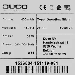
| Power Supply | 230V, 50/60Hz | Electrical power requirement | p. 4, 6 |
| RF Frequency | 868 MHz | Wireless communication frequency | p. 7 |
Where to find it in the PDF
- Mounting p. 5
- Control Valves p. 7, 8
- Calibration p. 13, 14
Table of contents
Manual images
Click an image to enlargeQuick guide from the manual
The DucoBox Focus is a demand-controlled ventilation unit that functions as both an extractor fan and a system controller. Installation must be performed by an accredited installer. Key steps include mounting the unit, connecting wiring, pairing control valves and components, and performing an air calibration procedure to ensure optimal performance.
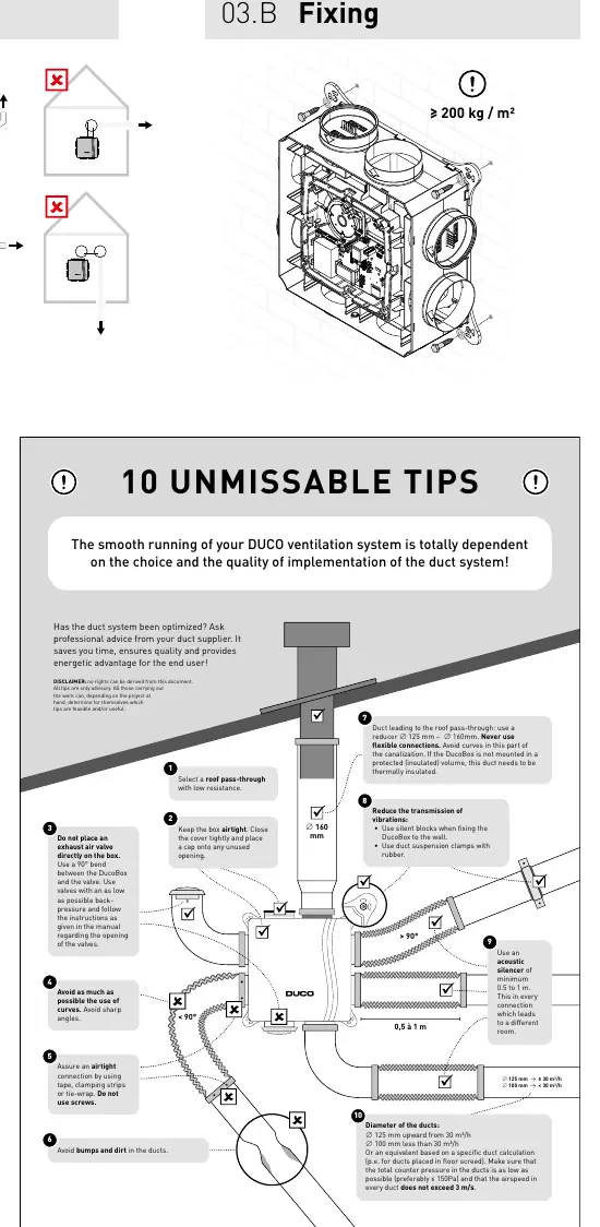
Mounting
The unit should be mounted in an enclosed space, at least 3m away from chimney pipes. Ensure the unit is fixed securely (≥ 200 kg/m²). Ducting must be connected before operation, with at least 900 mm of ducting attached to the unit. Avoid sharp bends and ensure airtight connections using tape or clamps.
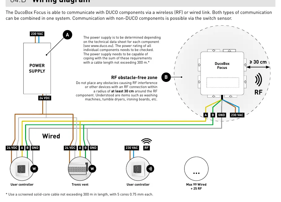
Wiring
The system supports both wired and wireless (RF) communication. The power supply must be 230V, 50/60Hz. Ensure the power cable is placed in the provided slot for strain relief. RF components should not have obstacles within a 30 cm radius. Wired connections use a 5-core 0.75 mm² cable.
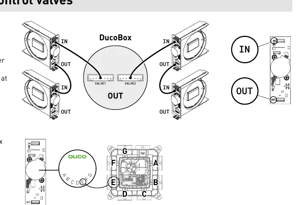
Control Valves
Up to 7 control valves can be installed (expandable to 11 with a manifold). Valves must be mounted in the designated locations. Use the letter labels (A-G) to ensure valves remain in the correct position. Valves are paired automatically when the system is in 'Installer mode'.
Electronical Installation
To add or replace components, the system must be in 'Installer mode'. This is activated by pressing the 'INST' button on the DucoBox. The LED status indicates the current mode (e.g., flashing green for pairing). The system reverts to 'User mode' after 15 minutes of inactivity.
Flow Rate Calibration
Calibration is essential for quiet and energy-efficient operation. It must be performed on a calm day. Before starting, close all windows and doors, ensure duct openings are closed, and set window ventilators to the open position. The system configures automatically upon power-up. Calibration takes 30 seconds plus 1 minute per connected control valve.
Maintenance
Regular inspection and cleaning are recommended. For service issues, contact your installer or retailer and have the product serial number ready.
Manufacturer information
Duco Ventilation & Sun Control NV
Practical help
Common problems
System not working correctly
Check if the DucoBox has been calibrated. Restart the unit and follow the '10 essential tips' if the problem persists.
RF interference
Ensure no obstacles (e.g., washing machines, tumble dryers) are within a 30 cm radius of RF components.
Component not pairing
Ensure you are within 30 minutes of pairing or restarting the component. Check that the system is in 'Installer mode'.
Before use
- Ensure power supply is 230V, 50/60Hz.
- Verify the unit is undamaged upon unpacking.
- Ensure at least 900 mm of ducting is connected before operation.
- Check that all duct openings are closed and the cover is secure.
- Ensure no obstacles are within 30 cm of RF components.
Specs in practice
- RF Frequency
- 868 MHz
- Max RF Range
- 350m in free field (less through obstacles)
- Max Wired Distance
- Up to 300m
- Max Control Valves
- 7 (expandable to 11 with manifold)
Images and diagrams
- Wiring diagram: Shows power supply (230V) and communication connections (Wired/RF).
- Control valve mounting: Illustrates how to slide valves into the DucoBox and connect them.
- Calibration situations: Shows how to set vents based on flow rate requirements.
Model compatibility
- Control valve with combined CO2 and RH measurement requires software version 11.2 or higher.
- Not compatible with (motorless) extractor hoods or tumble dryers.

Manual page author
David Miller
Documentation analyst
Organizes user manual content into clear summaries, with attention to model details, product context, and everyday usability.