HVAC / Ventilation Systems
Installation Guide for DucoBox Silent Connect
Comprehensive installation and configuration guide for the DucoBox Silent Connect ventilation unit. Includes mounting instructions, wiring diagrams, air calibration procedures, and system setup.
Quick answers from the manual
Quick answer
- The DucoBox Silent Connect is a ventilation unit acting as an extractor fan and system controller. Installation must be performed by an accredited installer. p. 3
Key actions
- Activate Installer Mode p. 12, 13
- Perform Air Calibration p. 15, 16
First start
- Ensure 230V power supply and connect at least 900mm of ducting. p. 7, 8
Problems and fixes
Orange LED
System not calibrated. Restart DucoBox.
p. 12
Red LED (slow blinking)
Component not in network.
p. 12Maintenance and reset
- Restore factory settings p. 14
Technical specifications
| Parameter | Value | Meaning | Pages |
|---|---|---|---|
| Power Supply | 230 VAC | Main power input | p. 7, 10 |
| RF Frequency | 868 MHz | Wireless communication frequency | p. 10 |
Where to find it in the PDF
- Mounting p. 8
- Air Calibration p. 15, 16
Table of contents
Manual images
Click an image to enlargeQuick guide from the manual
The DucoBox Silent Connect is a ventilation unit that functions as both an extractor fan and a system controller. This guide provides essential information for installation, wiring, and calibration. Installation, connection, maintenance, and repairs must be carried out by an accredited installer.
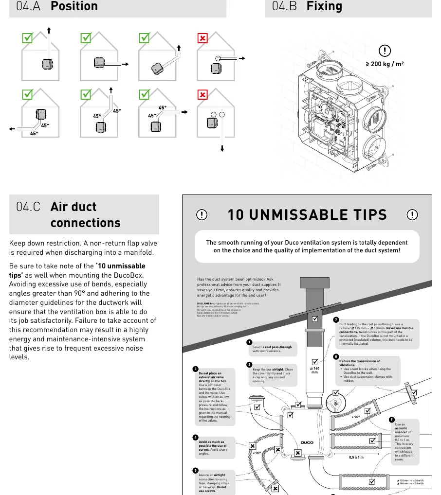
Mounting
The unit should be mounted in an enclosed space, at least 3 meters away from any chimney pipe. Ensure the unit is not subjected to direct water spraying. Before operation, at least 900 mm of ducting must be connected to the unit. Do not connect the DucoBox to an extractor hood or tumble dryer. Ensure the unit is mounted in a touch-safe manner.
Wiring
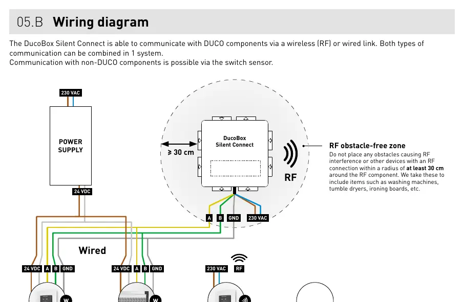
The system supports both wireless (RF) and wired communication, which can be combined. RF components have a maximum free-field range of 350 meters. Wired components should be daisy-chained using a 5 x 0.75 mm² shielded data cable. Ensure no obstacles causing RF interference (e.g., washing machines) are within 30 cm of the RF component.
Additional control options
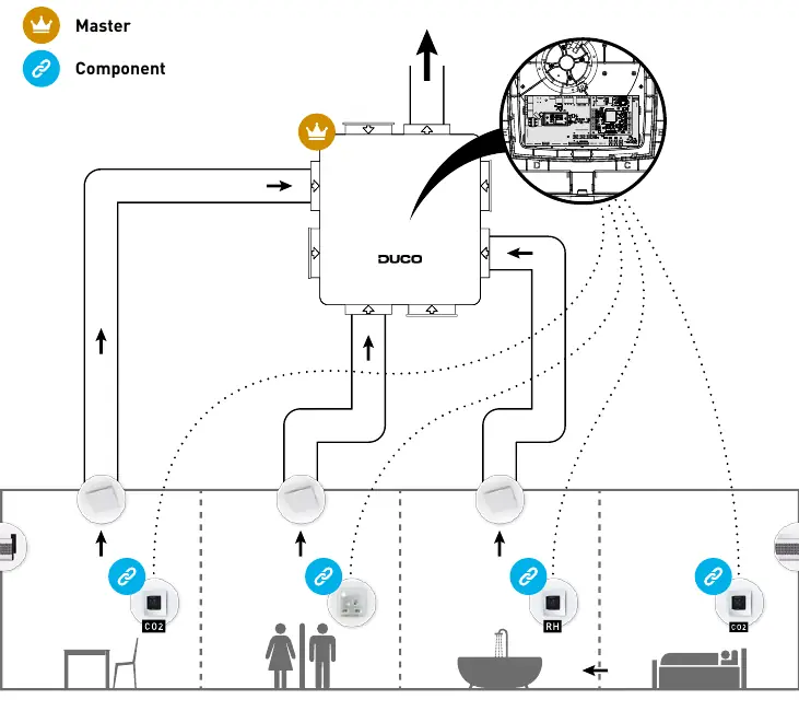
Box sensors for CO2 and humidity can be installed directly into the duct. A maximum of one CO2 and one Humidity sensor can be used per unit. The optional Duco Connectivity Board allows for home automation integration via REST API or Modbus TCP.
Electronical installation
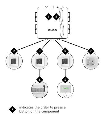
To add or remove components, the system must be in 'Installer mode'. This is activated by pressing the 'INST' button on the DucoBox. The LED will flash green when active. The system automatically reverts to 'User mode' after 15 minutes of inactivity.
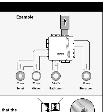
Air calibration
Air calibration is required for quiet and energy-efficient operation. This procedure must be performed on a calm day (wind force 2 or less). Ensure all windows and doors are closed, and all duct openings are sealed. Use the 'HIGH' or 'LOW' configuration modes to set the system for 30 minutes during calibration.
Maintenance and service
Regular maintenance is recommended. For service problems, contact your installer or retailer and have the serial number of the product ready.
Manufacturer information
Duco Ventilation & Sun Control NV
Practical help
Common problems
System not working correctly (Orange LED)
The system is not calibrated. Restart the DucoBox and follow the '10 essential tips' if the problem persists.
RF interference
Ensure no obstacles (e.g., washing machines, tumble dryers) are within 30 cm of the RF component.
Pairing issues
Ensure the system is in 'Installer mode' (LED flashing green) before attempting to pair components.
Before use
- Check that the unit is complete and undamaged upon unpacking.
- Ensure the power supply is 230 V, single-phase earthed.
- Verify that at least 900 mm of ducting is connected.
- Ensure the installation area is not excessively greasy or corrosive.
- Check that the unit is at least 3 m away from chimney pipes.
- Ensure a non-return flap valve is installed if discharging into a manifold.
Specs in practice
- RF Frequency
- 868 MHz
- Max RF Range
- 350 m (free field, less through obstacles)
- Max Flow Rate
- Up to 400 m³/h (model dependent)
Images and diagrams
- System overview showing Master and Component relationships.
- Wiring diagram illustrating RF and Wired connections.
- Pairing sequence diagram showing the order of button presses.
- Air calibration example showing vent flow rates.
Model compatibility
- Not suitable for industrial use (e.g., swimming pools, saunas).
- Do not connect to extractor hoods.
- Requires accredited installer for all connections.

Manual page author
Emily Carter
User documentation editor
Prepares concise manual descriptions and highlights the most useful setup, operation, and maintenance information for readers.