Accessories / Mounts & Stands
Installation Guide for Easee Base Charging Post
Comprehensive installation guide for the Easee Base modular charging post. Includes step-by-step instructions for 1-Way, 2-Way, and 4-Way configurations, power rail wiring, grounding, and technical specifications.
Table of contents
Manual images
Click an image to enlargeQuick guide from the manual
The Easee Base is a modular charging post designed to support up to four Easee Charging Robots. It is available in three configurations: 1-Way, 2-Way, and 4-Way. Important: Turn off the power before beginning any installation work. This product must be installed by an authorized electrician, and a declaration of conformity must be provided upon completion.
Common parts
The system consists of several shared components regardless of the configuration:
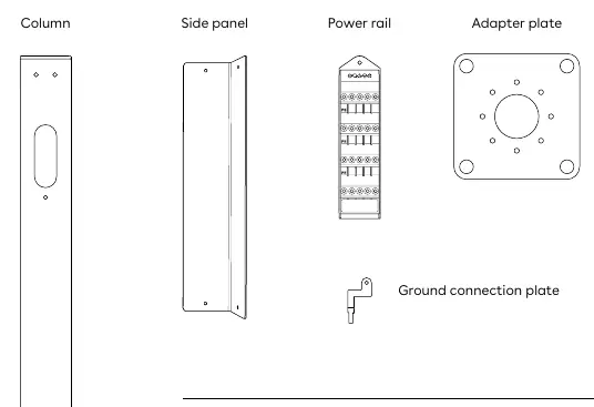
- Column
- Side panel
- Power rail
- Adapter plate
- Ground connection plate
- Screws, washers, and nuts
Installation configurations
The installation process varies based on the chosen setup:
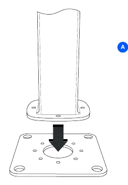
- Adapter plate: Attach the foundation of the column to the adapter plate using 4 hex socket screws. It can be mounted in 45° increments to achieve the correct direction. Recommended torque is 30-40Nm.
- 1-Way: Attach the mounting plate and blind cover to the column using 3 countersink screws each (6 total). Thread the cable through the column and charger backplate before attaching with 4 button screws.
- 2-Way: Attach two mounting plates to the column using 3 countersink screws each (6 total). Thread cables through the column and backplates before securing with 4 button screws per charger (8 total).
- 4-Way: Slide the bottom frame over the column and fasten with 1 countersink screw on each side. Attach the top frame using 2 countersink screws on each side. Cover with the top plate and fix with 4 button screws. Attach the 4 charger backplates using 4 button screws each.
Power rail installation
The Power rail is a connection box for series connection of charging posts. Proper grounding is critical:
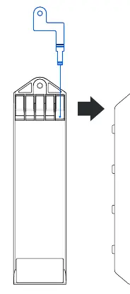
- Apply the ground connection plate by wedging it into the top PE terminal screw from the back. It must lie flat against the housing.
- Insert the serrated washer on the rod inside the column between the metal column and the Power rail.
- Slide the Power rail into the column and latch it.
- Fasten the grounding nut with the spring washer on the rod. Important: The grounding nut must be fastened and the top PE terminal screw must be tightened, even if no wire is present.
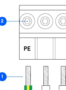
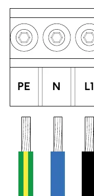
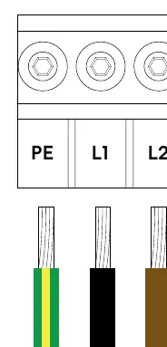
Wiring and grid types
The Power rail supports TN and IT grids (both 3-phase and 1-phase). Strip cable cores to 12mm. Tighten terminal screws with a torque of 5Nm. Ensure all terminations are visually and mechanically inspected before mounting the side panel.
Recommendations
- Foundation: Compatible with 160x160 center-to-center foundations (e.g., Ørstafundament). A 70x70 footprint is possible without the adapter plate.
- Torque: Use 7-9Nm for all countersink and button screws.
- Tools: All screws except the U6 Hex Socket fit a T25 tool.
- Protection: Do not use high-pressure water jets for cleaning.
Manufacturer information
Easee
Practical help
Common problems
Grounding failure
Ensure the ground connection plate is flat against the housing and the top PE terminal screw is tightened.
Incorrect column orientation
The adapter plate can be mounted in 45° increments to adjust the direction.
Loose connections
Ensure all terminal screws are tightened to 5Nm and all structural screws to 7-9Nm.
Before use
- Turn off the power supply before starting installation.
- Verify you have the correct parts for your configuration (1-Way, 2-Way, or 4-Way).
- Ensure the foundation is compatible (160x160 or 70x70 footprint).
- Have a T25 tool ready for assembly.
- Ensure an authorized electrician performs the installation.
Specs in practice
- Adapter plate torque
- 30-40Nm
- Screw torque
- 7-9Nm
- Terminal screw torque
- 5Nm
- Main cable wire size
- Up to 25mm²
- Charger cable wire size
- Up to 6mm²
Images and diagrams
- Power rail wiring diagrams show connections for TN 3-phase, TN 1-phase, IT 3-phase, and IT 1-phase grids.
- Grounding diagrams illustrate the correct placement of the ground connection plate and serrated washer.
Model compatibility
- Compatible with Easee Charging Robots.
- Supports TN and IT electrical grids.

Manual page author
Emily Carter
User documentation editor
Prepares concise manual descriptions and highlights the most useful setup, operation, and maintenance information for readers.