Accessories / Mounts & Stands
Easee Base 1-Way and 2-Way Charging Post Installation Manual
Installation and assembly guide for the Easee Base modular charging post. Includes wiring instructions, technical specifications, and safety requirements for 1-Way and 2-Way configurations.
Table of contents
Manual images
Click an image to enlargeQuick guide from the manual
The Easee Base is a modular charging post designed for Easee Charging Robots. Important: This product must only be installed, repaired, or serviced by an authorized electrician. All local, regional, and national regulations for electrical installations must be respected. The circuit must be RCD protected. Always turn off the power before beginning any wiring work.
Introduction
The Easee Base is a modular charging post that supports multiple configurations: 1-Way (one charger), 2-Way (two chargers), and 4-Way (up to four chargers). The system shares common parts, with only a few components specific to each layout.
Technical specifications
- Dimensions: H: 1500 x W: 160 x D: 80 mm
- Weight: 6.1–7.7 kg
- Material: Aluminium and stainless steel
- IP degree: IP44
- Impact resistance: IK10
- Cable size: Max 16mm² flexible conductors with ferrules; 25mm² solid conductors
- Conductor material: CU or ALU
Safety instructions
- Electrical Danger: High voltage. Never make changes to components or connecting cables.
- Environment: Do not install in explosive atmospheres or areas with flowing water.
- Maintenance: Do not use water for fire extinguishing. Never clean with high-pressure or running water.
- Operation: Do not use extension cords or unapproved adapters. Protect from direct sunlight or extreme weather if possible.
Assembly instructions
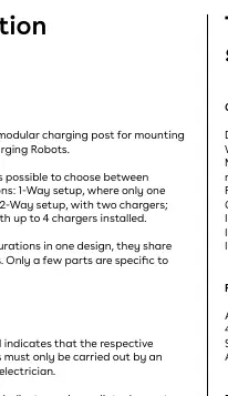
Adapter plate
Attach the foundation of the column to the adapter plate using 4 socket head screws. The recommended torque is 30-40 Nm. The plate can be mounted in 45° increments to achieve the correct direction.
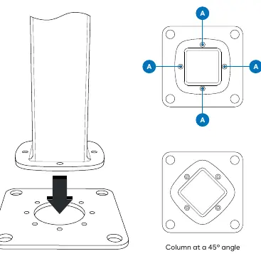
1-Way configuration
- Attach the mounting plate to the column with 3 flat head screws.
- Attach the cover with 3 rounded head screws.
- Ensure the top end of the column is sealed with a plastic cap.
- Thread the cable through the hole in the column and the Easee charger backplate before attaching it with 4 rounded head screws.
2-Way configuration
- Attach the mounting plates to the column with 3 flat head screws each (6 screws total).
- Ensure the top end of the column is sealed with a plastic cap.
- Thread the cables through each hole in the column and the Easee charger backplates before attaching them with 4 rounded head screws (8 screws total).
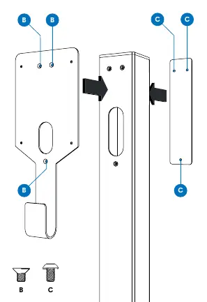
Power Rail installation
The Power Rail is a connection box allowing multiple charging posts to be connected in series.
- Ground connection: Apply the ground connection plate before installing the Power Rail. Wedge the end of the plate into the top PE terminal from the back.
- Mounting: Insert the serrated washer on the rod inside the column between the metal column and the Power Rail. Slide the Power Rail inside and latch the bottom.
- Fastening: Fasten the grounding nut with the spring washer on the rod. The top PE terminal screw must be tightened regardless of whether a wire is inserted.
- Wiring: Strip wires by 12 mm. Use ferrules on stranded wires. Tighten screw terminals to 5 Nm. Use dielectric grease for ALU conductors.
Side panel
After connecting all wires to the Power Rail, mount the side panel using the 4 rounded head screws.
Manufacturer information
Easee
Practical help
Common problems
Installation by unauthorized personnel
The product must only be installed, repaired, or serviced by an authorized electrician.
Circuit protection
Connection via Power Rail requires the circuit to be RCD protected.
Cleaning issues
Never clean the product with high pressure or running water; do not immerse in water.
PE connection failure
Ensure the grounding nut is fastened and the top PE terminal screw is tightened, even if no wire is present.
Before use
- Ensure the installation location is permanent.
- Verify the foundation is compatible (c/c 160 mm).
- Turn off the power before beginning wiring.
- Use ferrules on stranded wires.
- Apply dielectric grease when using ALU conductors.
- Test wire connections by pulling on each wire before turning on power.
Specs in practice
- Torque (Adapter plate)
- 30-40 Nm for foundation screws.
- Torque (Screw terminals)
- 5 Nm for electrical connections.
- Torque (Side panel/mounting screws)
- 7-9 Nm.
Images and diagrams
- Adapter plate: Can be rotated in 45-degree increments.
- Ground connection plate: Must lie flat against the plastic housing.
- Wiring: Supports TN/TT 3-phase, IT/TT 3-phase, TN 1-phase, and IT/TT 1-phase configurations.
- PE lane: The leftmost lane on the Power Rail is reserved for PE connections.
Model compatibility
- Compatible with c/c 160 mm foundations.
- Can be installed without adapter plate using 80x80 center-to-center footprint.
- Supports up to 4 Easee Charging Robots.

Manual page author
David Miller
Documentation analyst
Organizes user manual content into clear summaries, with attention to model details, product context, and everyday usability.