Power / Energy Storage Systems
User Manual for EG4-LiFePower4 12V 400AH Battery
Quick guide for the EG4-LiFePower4 12V 400AH battery. Includes installation steps, DIP switch settings, LED indicator meanings, troubleshooting, and software setup.
Table of contents
Manual images
Click an image to enlargeQuick Guide and Safety Information
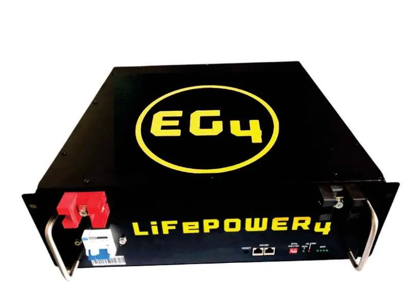
The EG4-LiFePower4 12V 400AH is a lithium iron phosphate battery module designed for solar systems, off-grid living, and energy storage. Installation must be performed by a knowledgeable and qualified professional. Before starting, ensure all power systems are in the OFF state, remove metallic jewelry, and use insulated tools.
Product Overview and Specifications
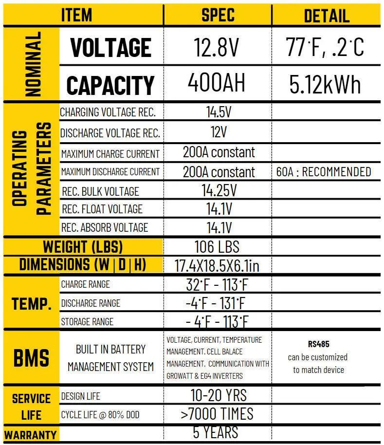
The battery features an integrated Battery Management System (BMS) for monitoring and protection. Key specifications include a nominal voltage of 12.8V, 400AH capacity, and 5120WH energy. It supports a constant charge/discharge current of 200A. The operating temperature range is -4°F to 131°F.
Installation and Setup
Installation involves mechanical mounting, electrical connection, and commissioning. Ensure the battery is mounted in a 19-inch rack or cabinet using the provided handles and mounting lugs. Ground the battery using the chassis rear grounding hole. When connecting multiple batteries in parallel, use a copper bus-bar. Ensure all power sources are off before connecting. After installation, turn on each battery module one at a time, pausing between each to allow stabilization.
LED Indicators and DIP Switches
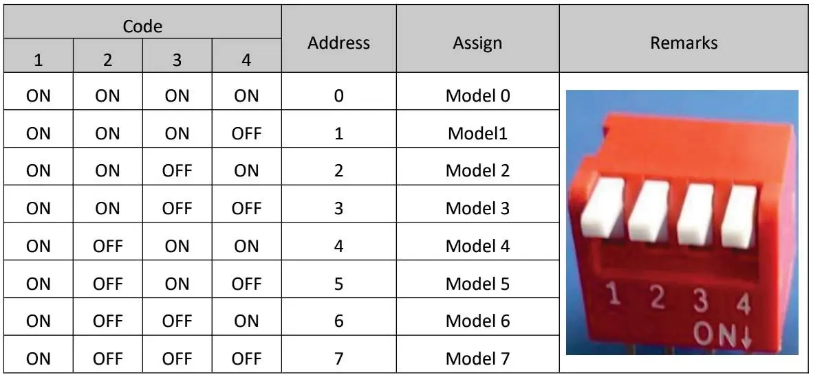
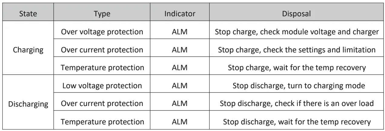
The battery features LED indicators for RUN, ALM (Alarm), and SOC (State of Charge). The DIP switches are used to assign addresses (0-7) when cascading up to 16 modules. Ensure no duplicate address codes are used. The RUN and ALM lights provide real-time status updates regarding charging, discharging, and protection modes.
PC Software Configuration
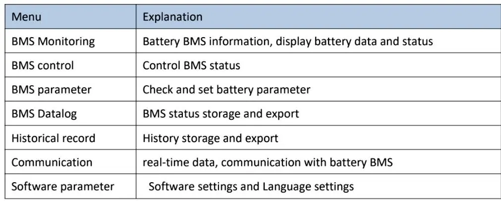
The battery can be monitored via PC software. Connect the battery communication port (RS485 or DB9) to your PC. Set the baud rate to 9600 and click Search Device to connect. The software allows for monitoring battery data, BMS control, and parameter settings.
Troubleshooting and Maintenance
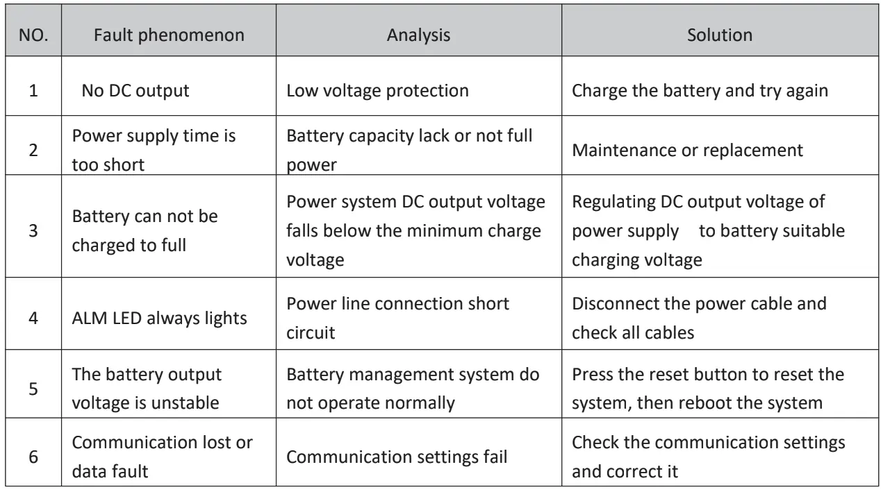
If the ALM light is on, the battery is in a protection or alarm state. Common faults include no DC output (often due to low voltage protection), inability to charge fully (check power supply voltage), or unstable output. If the ALM light persists or circuit breakers trip, immediately turn off all power sources and inspect the connections. For long-term storage, charge and discharge the battery every three months, keeping the state of charge between 50% and 60%.
Manufacturer information
EG4 Electronics
Practical help
Common problems
No DC output
Check for low voltage protection; charge the battery and try again.
Battery cannot be charged to full
Regulate the DC output voltage of the power supply to match the battery's suitable charging voltage.
ALM LED always lights
Indicates a power line connection short circuit; disconnect the power cable and check all cables.
Communication lost or data fault
Check the communication settings and correct them.
Before use
- Ensure installation is performed by a qualified professional.
- Remove metallic jewelry, watches, and rings.
- Use insulated tools.
- Ensure all power systems are in the OFF state.
- Check all cabling for exposed wiring or poor insulation.
- Ensure the battery is grounded.
Specs in practice
- Max Charge/Discharge Current
- 200A constant.
- Operating Temperature
- -4°F to 131°F.
Images and diagrams
- DIP Switch Address: Used to assign IDs (0-7) for parallel connection.
- LED Indicators: RUN and ALM lights indicate operational status and warnings.
- Installation Flow: Follow the step-by-step process from environment check to commissioning.
Model compatibility
- Expandable up to 16 units.
- Do not place batteries in series.
- Do not mix batteries from different manufacturers or types.
- Do not mix old and new batteries.

Manual page author
David Miller
Documentation analyst
Organizes user manual content into clear summaries, with attention to model details, product context, and everyday usability.