Power / Energy Storage Systems
User Manual for EG4 14.3kWh WallMount All Weather Battery
Quick guide for the EG4 14.3kWh WallMount All Weather Battery. Includes installation steps, wiring diagrams, BMS communication setup, troubleshooting, and technical specifications.
Table of contents
Manual images
Click an image to enlargeQuick guide from the manual
The EG4 14.3kWh WallMount All Weather Battery is a 48V lithium iron phosphate (LiFePO4) energy storage system designed for residential outdoor use. This manual provides essential instructions for safe installation, wiring, communication setup, and maintenance. Always ensure the battery is in the off position before making any connections and use a voltmeter to verify no voltage is present.
Safety Warnings
- Hazardous Voltage: Do not disassemble the battery. Incorrect servicing can result in electric shock or fire.
- Short Circuit: Never short-circuit DC inputs.
- Handling: The battery is heavy (308.6 lbs / 140 kg). Use a team lift technique or appropriate lifting equipment.
- Environment: Mount in an upright position on a non-combustible surface. Ensure proper drainage if installed on the ground.
- Temperature: The battery stops charging below 32°F (0°C). Disconnect immediately if charging current is observed below this temperature.
Installation
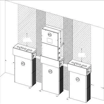
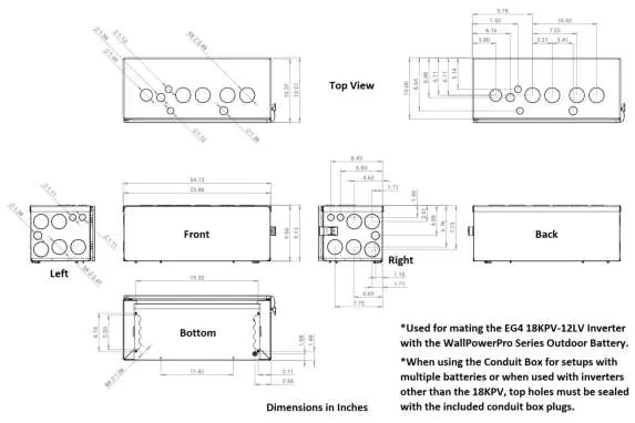
The battery can be installed with or without a conduit box and can be integrated with the EG4 18kPV inverter.
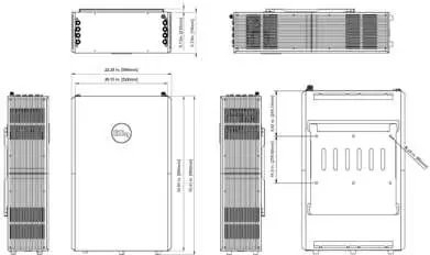
- Clearance: Maintain at least 6 inches (152.4 mm) of clearance on each side of the battery for airflow and access.
- Mounting: Secure the mounting bracket to the wall at a height of at least 28.0625 inches from the ground. Use the included expansion bolts for concrete/brick or appropriate hardware for other surfaces.
- Conduit Box: Highly recommended for cable protection. Attach to the top of the battery using the provided thumb screws.
- Grounding: Always attach a grounding conductor to the M6 grounding screw on top of the battery.
Battery Paralleling and Wiring
- Series Connection: Do not connect these batteries in series.
- Paralleling: Ensure all batteries are charged to 100% before paralleling. Use the paralleling kit (sold separately) for communication cables and power cables.
- Communication: Daisy-chain the "Battery-Comm" ports using the communication cable. The battery with DIP Switch ID 1 acts as the master and connects to the inverter.
Communication and Settings
- DIP Switches: Each battery in a parallel bank must have a unique ID (1-64). Set the master battery to ID 1.
- Protocol Selection: To change the inverter protocol, set the master battery to address 64, restart, and use the "Return" key for 5 seconds to enter the "Protocol Setting" menu.
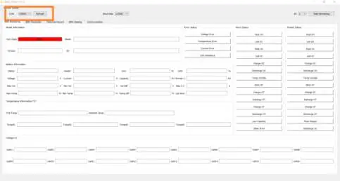
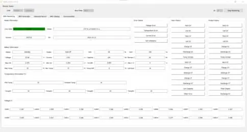
- BMS Tools: PC software is available for real-time diagnostics. Connect via an RS-485 to USB-A cable. Set the battery to ID 64 to communicate with the software.
Operation and LCD
The LCD screen displays voltage, current, temperature, and state of charge (SOC). Use the four buttons below the screen (Up, Down, Return, Enter) to navigate menus and view cell-level data.

Troubleshooting
If the ALM light is on, check the cause via the app or BMS Tools. Common issues include:
- Inverter communication failure: Check communication port connection and battery ID setting.
- No DC output: Check battery breaker or charge the battery.
- ALM LED always on: Indicates a short circuit; disconnect power cables and inspect.
- Unbalanced voltage/temperature: Deep discharge the battery bank (<20% SOC) and then charge fully.
Technical Specifications
- Energy Capacity: 14.3kWh @ 25°C, 100% SOC.
- Voltage: 51.2V nominal.
- Max Continuous Charge/Discharge: 200A.
- Ingress Protection: IP65.
- Cycle Life: >8000 cycles @ 0.5C, 80% DOD.
Storage and Disposal
Store the battery at 50% SOC in a location between 33°F and 90°F (0.6°C - 32°C). Recharge every 8-9 months during prolonged storage. Do not dispose of in trash; contact local recycling organizations for lithium battery disposal.
Manufacturer information
EG4 Electronics
Practical help
Common problems
Inverter communication failure
Check communication port connection and battery ID setting. Ensure the master battery is set to ID 1.
No DC output
Check if the battery breaker is open or if the battery voltage is too low. Charge the battery if necessary.
ALM LED always on
Indicates a short circuit. Disconnect the power cable and check all cables for damage.
Battery cannot be charged fully
Check the charging settings on the inverter to ensure they match the battery requirements.
Unbalanced voltage within a cell
Deep discharge the battery bank to below 20% SOC, then charge the battery bank fully.
Before use
- Ensure battery is in the off position before making connections.
- Use a voltmeter to confirm no voltage is present at terminals.
- Ensure all batteries are charged to 100% before paralleling.
- Set unique DIP switch IDs for each battery in the bank.
- Ensure wall mounting surface is non-combustible.
- Remove temporary lifting handles before connecting wiring.
Specs in practice
- Total Energy Capacity
- 14.3kWh at 25°C and 100% State of Charge.
- Max Continuous Current
- 200A for both charging and discharging.
- Ingress Protection (IP65)
- The unit is dust-tight and protected against water jets, suitable for outdoor use.
Images and diagrams
- Figure 3: Side panel layout identifying terminals, LCD, switches, and communication ports.
- Figure 17: Battery communication ports for daisy-chaining multiple units.
- Figure 27: DIP switch ID table for configuring master/slave addresses.
- Figure 32: Battery protocol selection menu for inverter compatibility.
Model compatibility
- Do not connect batteries in series.
- Compatible with EG4 18kPV inverter.
- Requires RS485/CAN communication for closed-loop inverter integration.

Manual page author
Emily Carter
User documentation editor
Prepares concise manual descriptions and highlights the most useful setup, operation, and maintenance information for readers.