Power / Energy Storage Systems
User Manual for EG4 14.3kWh PowerPro WallMount Battery
Quick guide for the EG4 14.3kWh PowerPro WallMount battery. Includes installation instructions, wiring diagrams for paralleling, communication setup, and troubleshooting steps.
Table of contents
Manual images
Click an image to enlargeQuick Start Guide
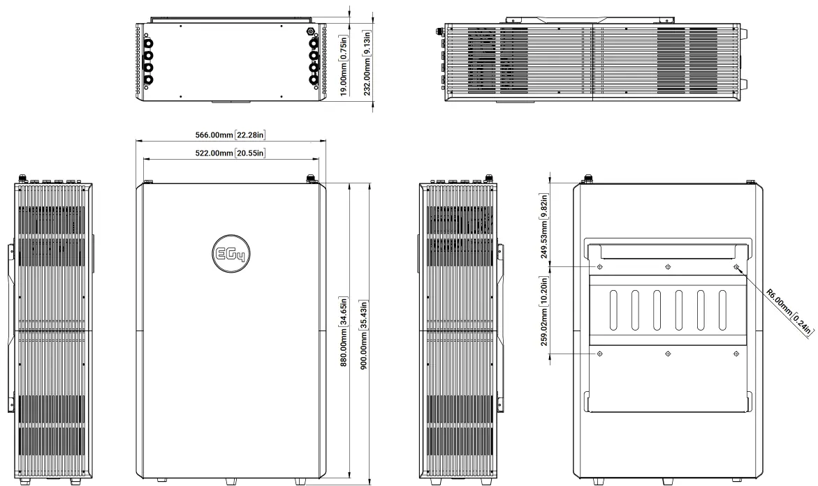
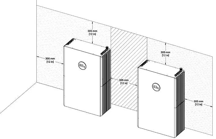
The EG4 14.3kWh PowerPro WallMount is an all-weather lithium iron phosphate (LiFePO4) battery designed for residential energy storage. Before installation, ensure the battery is in the OFF position. Use the team lift technique as the unit is heavy. Ensure at least 12 inches of clearance on all sides for proper airflow and maintenance access.
Safety Information
Warning: All work must be performed by qualified personnel. Do not disassemble the battery. Never short-circuit DC inputs. Ensure all battery breakers and switches are in the OFF position before making any connections. The battery must be installed in a location that prevents flooding and is away from direct sunlight or extreme heat.
Installation
The battery can be installed on flat ground or mounted on a wall. When wall mounting, use the provided mounting bracket and ensure it is secured into studs or concrete/brick using appropriate hardware. The battery hooks onto the mounting bracket and is secured with side screws. If using a conduit box, attach it to the top of the battery before final installation. Always ground the battery using the M6 grounding screw on top.
Battery Paralleling
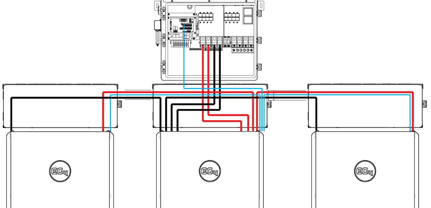
When paralleling multiple batteries, ensure all breakers and BMS are OFF. Set unique DIP switch IDs for each battery (starting with ID 1 for the master). Use the paralleling kit communication cable to daisy chain the batteries via the Battery-Comm ports. Connect the master battery to the inverter using the RS485/CAN port. Use the supplied 2/0 AWG cables for power connections.
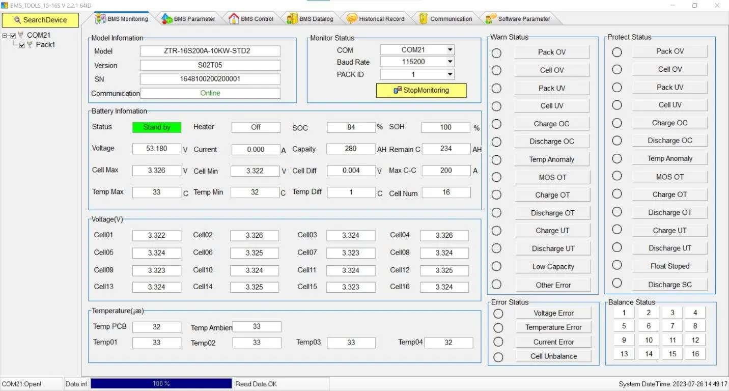
Communication and Monitoring
The battery features an LCD screen for real-time monitoring of voltage, current, temperature, and SOC. For advanced diagnostics, use the BMS Tools PC software. Connect the battery to a PC using the battery-to-PC USB cable via the RS485 port. Ensure the battery is set to Address 64 during the initial connection to BMS Tools.

Troubleshooting
If the ALM light is on, check the BMS Tools software or the battery site for the specific alarm. Common faults include inverter communication failure (check port connection and ID settings), no DC output (check breaker or charge level), and unstable power supply (check cable connections). If the battery is deeply discharged, contact the distributor.
Technical Specifications
The battery operates at a nominal 51.2V with a 280Ah capacity. It is IP65 rated for all-weather use. The charging range is 32°F to 113°F (0°C to 45°C), and the discharging range is -4°F to 122°F (-20°C to 50°C). The design life is over 15 years with more than 8000 cycles at 80% DOD.
Manufacturer information
EG4 Electronics
Practical help
Common problems
Inverter communication failure
Check communication port connection and battery ID setting. Input proper host battery DIP switch address and power cycle the battery.
No DC output
Check battery breaker or charge the battery if voltage is too low.
ALM LED always on
Disconnect the power cable and check all cables for short circuits.
Battery cannot be charged fully
Check the charging settings on the inverter to ensure they match battery requirements.
Before use
- Ensure battery is in the OFF position before making connections.
- Verify all wiring meets NEC and local codes.
- Use team lift technique for the heavy battery unit.
- Ensure at least 12-inch clearance on each side for airflow.
- Set DIP switch IDs correctly for paralleled batteries.
- Verify voltage between positive and negative busbars is 0V before installation.
Specs in practice
- Ingress Protection
- IP65 (all-weather rated)
Images and diagrams
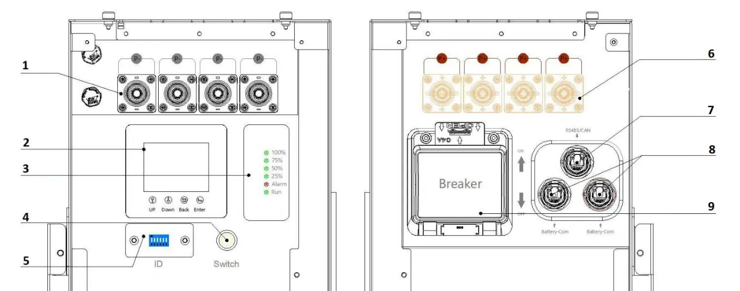
- Battery Diagram (Side View): Shows terminals, LCD screen, power switch, and communication ports.
- Wiring Diagrams: Illustrates paralleling configurations with inverters.
- DIP Switch Table: Reference for setting unique battery IDs.
Model compatibility
- Do not mix with non-280Ah lithium batteries.
- Do not connect batteries in series.
- Compatible with EG4 18kPV inverters.

Manual page author
David Miller
Documentation analyst
Organizes user manual content into clear summaries, with attention to model details, product context, and everyday usability.