Power / Solar Inverters
Wiring Diagram and Configuration Guide for Eco-Worthy 10kW AIO Inverter & Battery
Quick guide to wiring and configuring your Eco-Worthy 10kW AIO Inverter and Battery system. Includes diagrams for single-phase, split-phase, and three-phase setups with configuration codes.
Table of contents
Manual images
Click an image to enlargeQuick Guide to Wiring and Configuration
This document provides essential wiring diagrams and configuration settings for the Eco-Worthy 10kW AIO Inverter and Battery system. It covers various installation scenarios, including single-phase, split-phase, and three-phase configurations. Always ensure all power sources are disconnected before performing any wiring.
System Configurations
The manual details the following setup types:
- Single-phase: Configurations for one or two 10kW inverters.
- Split-phase: Configurations for one, two, or three 10kW inverters.
- Three-phase: Configuration for three 10kW inverters.
Configuration Settings
Each setup requires specific configuration codes to be entered into the inverter system. Common parameters include:
- [08] -- LF16: Inverter mode setting.
- [30] -- Device ID: Identifies the inverter in multi-unit setups (e.g., 1, 2, 3).
- [31] -- Phase/Protocol: Defines the phase output (e.g., SIG, PAL, 2P0, 2P1, 2P2).
- [32] -- 485: Communication setting.
- [33] -- PYL: Battery communication protocol.
- [38] -- 120: Voltage setting for specific split-phase configurations.
- [68] -- 0/180: Additional configuration parameter.
Refer to the specific section in the manual corresponding to your installation type to find the exact codes required for your setup.
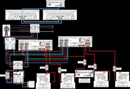
Wiring Diagrams
The manual contains detailed wiring diagrams for each configuration. These diagrams illustrate the connections for:
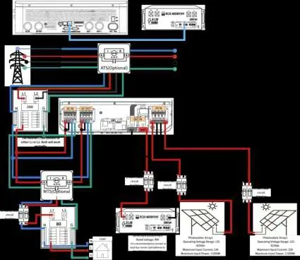
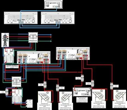
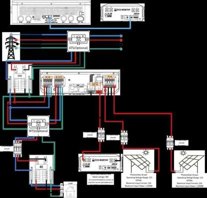
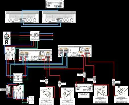
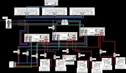
- AC Input and Output
- PV Array connections
- Battery bank connections
- ATS (Automatic Transfer Switch) and MTS (Manual Transfer Switch) integration where applicable
Ensure that your physical wiring matches the color-coded lines (L1, L2, N, G) shown in the diagram for your specific configuration.
Support
For further assistance, you can contact the manufacturer via email at [email protected] or visit their website at https://www.eco-worthy.com/.
Official resources from the manual
Practical help
Common problems
Inverter not communicating in multi-unit setup
Verify that the [30]--Device ID is unique for each inverter and that [32]--485 and [33]--PYL settings are correctly configured.
Incorrect phase output
Check the [31]--Phase setting. Ensure it matches the specific requirement for your single-phase, split-phase, or three-phase configuration.
Before use
- Ensure all AC and DC breakers are turned off before starting installation.
- Verify the number of inverters matches your intended phase configuration (Single, Split, or Three-phase).
- Confirm battery voltage compatibility.
- Check all cable connections against the specific diagram for your setup.
- Ensure all configuration codes ([08], [30], [31], etc.) are set correctly on each unit.
Specs in practice
- [30]--Device ID
- Sets the ID for the inverter (1, 2, or 3) to allow communication in parallel or multi-phase systems.
Images and diagrams
- Diagrams show the physical wiring path for AC input/output, PV arrays, and battery banks.
- Color-coded lines represent L1, L2, N, and Ground connections.
- Optional components like ATS and MTS are indicated in the diagrams.
Model compatibility
- Supports single-phase, split-phase, and three-phase configurations.
- Requires specific configuration codes for each setup type.

Manual page author
Michael Turner
Technical manual editor
Reviews PDF manuals for structure, safety notes, and practical product details so readers can find the right information quickly.