Power / Solar Inverters
Installation Guide for Sungrow 1-Phase Hybrid Inverter SH3.0RS / SH3.6RS / SH4.0RS / SH5.0RS / SH6.0RS
Quick installation guide for Sungrow 1-Phase Hybrid Inverters (SH3.0RS to SH6.0RS). Includes safety instructions, mounting steps, wiring diagrams for AC/DC/Battery, and LED status definitions.
Table of contents
Manual images
Click an image to enlargeQuick Guide from the Manual
This guide provides essential installation and safety information for the Sungrow 1-Phase Hybrid Inverter series (SH3.0RS, SH3.6RS, SH4.0RS, SH5.0RS, SH6.0RS). All operations must be performed by qualified personnel trained in electrical installation and safety regulations. Always refer to the full user manual for detailed configurations.
Safety Instructions
- Lethal Voltage: PV strings produce electrical power when exposed to sunlight. Only qualified personnel should perform wiring.
- Maintenance: Disconnect the inverter from all external power sources before maintenance. Wait at least 10 minutes after disconnection for internal capacitors to discharge.
- Hot Surfaces: The inverter surface can exceed 60°C. Do not touch hot parts during operation.
- Handling: Do not open the enclosure. Unauthorized opening voids the warranty. Wear a grounding wristband when handling electronic components to prevent electrostatic discharge (ESD).
Mounting
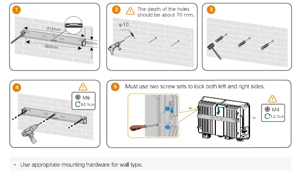
- Ensure the mounting surface is suitable and can support the weight of the inverter.
- Use the provided wall-mounting bracket.
- Drill holes (approx. 70mm depth) using a 10mm drill bit.
- Secure the bracket using the provided screw sets.
- Lock the inverter onto the bracket using the M4 screws on both left and right sides.
Wiring
PE (Protective Earth): Ensure the cable is intact and properly insulated. Connect the PE cable according to local regulations.
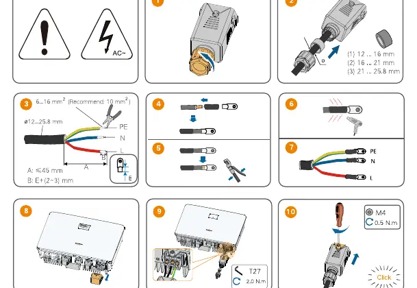
AC Connection: Use the provided grid connector. Ensure the cable diameter matches the connector specifications (12–25.8 mm). Tighten the connector to 5.0–6.0 N.m.
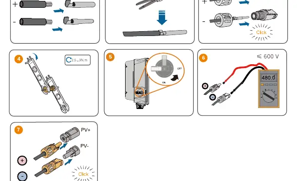
DC Connection: PV3 and PV4 are not applicable to the Hybrid inverter. Connect PV strings to PV1 and PV2 ports. Ensure correct polarity.
Battery Connection: Refer to the battery manufacturer's instructions for specific connection and configuration requirements.
Communication: Install the WiNet-S module or Ethernet cable for communication. Refer to the pinout diagrams for Meter, RS485, CAN, and DRM connections.
Startup and LED Indicators
To power on the system, switch on the AC breaker and the DC switch. The LED indicator on the front panel provides system status:
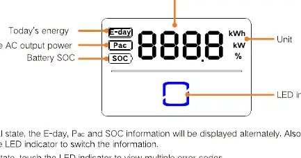
- ON (Blue): Operating normally.
- Twinkling (Blue): Standby or startup state.
- ON (Red): System fault.
- OFF: Powered down.
Touch the LED indicator to cycle through information like Today's energy (E-day), Real-time AC output power (Pac), and Battery SOC.
Practical help
Common problems
Inverter not starting
Ensure AC and DC switches are ON. Wait 10 minutes after disconnection for internal capacitors to discharge.
Communication error
Check RS485/CAN wiring and pinout. Ensure WiNet-S module is properly seated.
Battery not detected
Verify battery communication settings and cable connections.
Before use
- Check package contents against the packing list.
- Ensure mounting surface is suitable and can support the weight.
- Verify all cables are intact and properly insulated.
- Wear appropriate Personal Protective Equipment (PPE).
- Ensure the inverter is disconnected from all power sources before maintenance.
Specs in practice
- Operating Temperature
- -25°C to +60°C.
Images and diagrams
- Wiring diagrams illustrate connections for PV, Battery, Grid, and Backup loads.
- LED panel displays energy, power, and battery status.
Model compatibility
- Compatible with specific battery types; refer to battery manufacturer instructions.
- Installation and country settings must be performed by qualified personnel only.

Manual page author
Emily Carter
User documentation editor
Prepares concise manual descriptions and highlights the most useful setup, operation, and maintenance information for readers.