Industrial / Data Loggers
Growatt MOD 7-15KTL3-X Series Solar Inverter Quick Guide
Quick guide for installing and operating the Growatt MOD 7-15KTL3-X series solar inverters. Includes mounting instructions, electrical connection diagrams, power-on procedures, and status indicator explanations.
Table of contents
Manual images
Click an image to enlargeQuick Guide Overview
This document provides essential installation and operation instructions for the Growatt MOD 7-15KTL3-X, MOD 7-11KTL3-X-AU, and MOD 12-15KTL3-X(NDS) series solar inverters. It covers mounting, electrical connections, and basic system operation.
Installation Requirements
Ensure the installation site meets the following requirements:
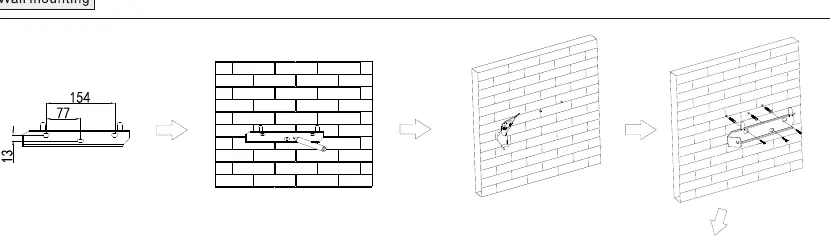
- Maintain a clearance of at least 300mm around the inverter for ventilation.
- The wall must be suitable for mounting the inverter weight.
- Avoid drilling holes in areas with water or electricity pipes.
Electrical Connection
Before connecting cables, ensure all switches are in the OFF position. Use the following guidelines for cabling:
- Protective Grounding: Single multi-core yellow-green wire (6mm²).
- AC Output: Two or three polychromatic multi-core copper wires (6mm²).
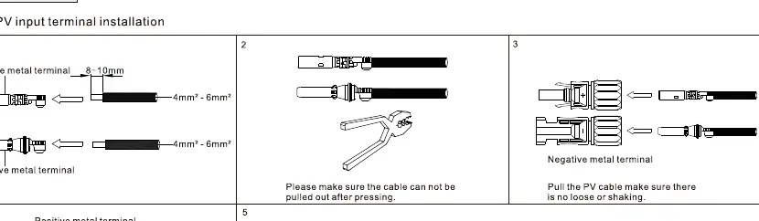
- PV Input: PV wire (e.g., PV1-F, 4mm²-6mm²).
- Communication: RS485 cable.
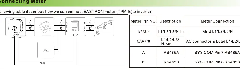
Connecting the Meter
The inverter supports connection to an EASTRON TPM-E meter. Connect the meter pins (1/2/3/4 for L1/L2/L3/N-in and 5/6/7/8 for L1/L2/L3/N-out) to the corresponding inverter terminals using RS485 communication (A to SYS COM Pin 7, B to SYS COM Pin 8).
Post-Installation Check
Before powering on, verify the following:
- The inverter is installed correctly and firmly.
- The ground wire is connected well and is reliable.
- All switches are in the OFF state.
- All wiring is correct and securely connected.
- The cable tie port is trimmed well without leaving sharp corners.
- All exposed terminals are protected.
Power On and Off Steps
Power On:
- Turn on the build-in DC isolator at the bottom of the inverter.
- Turn on the PV Array and DC isolator next to the inverter.
- Turn on the AC isolator if it is more than 3 meters away.
- Turn on the solar main supply switch in the switch board.
Power Off: Follow the power-on steps in reverse order.
Status Indicators
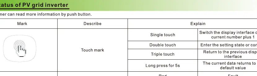
The inverter features a touch button and LED indicator:
- Single touch: Switch display interface.
- Double touch: Enter setting state or confirm.
- Triple touch: Return to previous display interface.
- Long press (5s): Return to default value.
LED status: Red indicates a fault, Green indicates normal operation, and Red light flashing indicates a warning.
Export Limitation Setting
If the local grid requires output power limitation, use the Export Limit Rate feature. This is calculated as the ratio of the system output power divided by the rated power of the inverter. Access this via the advanced settings menu.
Service and Contact
For support, contact Shenzhen Growatt New Energy Co., Ltd. Address: 4-13/F,Building A,Sino-German(Europe) Industrial Park, Hangcheng Ave,Guxing Community,Xixiang Subdistrict, Bao'an District, Shenzhen, China. Phone: +86 0755 2747 1942. Email: [email protected]. Website: www.ginverter.com.
Official resources from the manual
Manufacturer information
Growatt New Energy
Practical help
Common problems
Cable diameter mismatch
Ensure the cable diameter matches the terminal requirements (e.g., 6mm² for AC output).
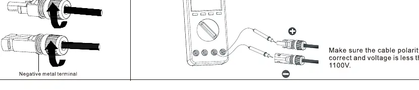
PV input voltage error
Ensure PV input voltage is less than 1100V and polarity is correct.
Communication failure
Verify RS485 wiring connections (A/B pins) and ensure the cable is securely plugged in.
Before use
- Ensure all switches are in the OFF position before wiring.
- Verify that the wall mounting surface is suitable.
- Check that the PV input voltage is within MPPT limits.
- Confirm that the AC output cable is the correct type (multi-core copper).
- Ensure all exposed terminals are protected and no wires are loose.
Specs in practice
- PV Input Voltage
- Must be less than 1100V.
- Recommended Cable (AC/Ground)
- 6mm² multi-core copper wire.
Images and diagrams
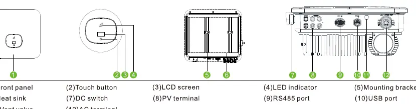
- The overview diagram identifies the front panel, touch button, LCD screen, LED indicator, mounting bracket, heat sink, DC switch, PV terminal, RS485 port, USB port, and AC terminal.
- The AC connection diagram shows the assembly of the AC connector, including stripping the cable and securing the wires.
- The PV connection diagram illustrates the positive and negative terminal assembly and the importance of checking polarity.
Model compatibility
- Compatible with EASTRON TPM-E meter for export limitation.
- Supports RS485 communication for monitoring and meter connection.

Manual page author
Michael Turner
Technical manual editor
Reviews PDF manuals for structure, safety notes, and practical product details so readers can find the right information quickly.