Electronics / Monitors
User Manual for Ernitec 0070-24124-POE CCTV Monitor
Quick guide for the Ernitec 0070-24124-POE CCTV monitor. Learn how to connect, configure OSD settings, troubleshoot common issues, and perform maintenance.
Table of contents
Manual images
Click an image to enlargeQuick guide from the manual
This monitor is designed for CCTV applications. Before operating, ensure the device is placed on a stable surface, connected to a grounded power outlet, and that all cables are securely attached. If you encounter issues, check the input source, cable connections, and OSD settings. Always unplug the monitor during lightning storms or extended periods of non-use.
Introduction
The Ernitec 0070-24124-POE monitor includes the following accessories: a power cable, a power cord, a remote control, and this user manual. The front panel features basic controls for input selection, menu navigation, and power.

Installation and Connections
Power Connection: Connect the power cord to the monitor and a wall outlet. The power indicator on the front panel will light up green when powered on.
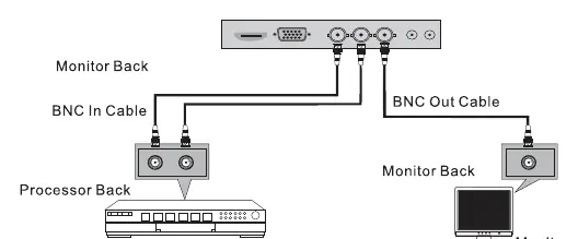
External Equipment: The monitor supports various inputs including HDMI, VGA, and BNC. To connect a PC, use the VGA or HDMI ports. For CCTV systems, use the BNC input/output ports to daisy-chain monitors or connect to processors.
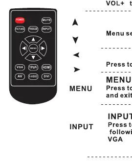
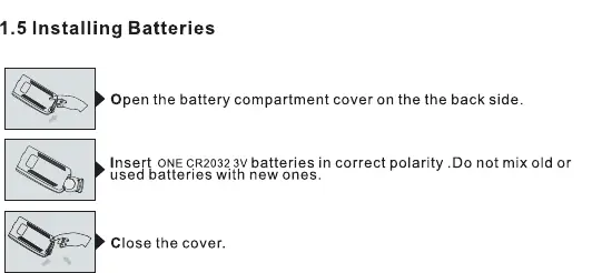
Remote Control: Install one CR2032 3V battery into the remote control, ensuring correct polarity. Point the remote towards the sensor on the monitor within a 7-meter range.
Basic OSD Setup
The On-Screen Display (OSD) menu allows you to customize monitor performance:
- Menu Navigation: Press the MENU button to access the main interface. Use the arrow buttons to navigate and select submenus.
- Picture Adjust: Modify settings such as Contrast, Brightness, Color, Sharpness, and Tint.
- ColorTemp Adjust: Change color temperature settings (e.g., Red, Green, Blue gain).
- Aspect Ratio: Toggle between 4:3 and 16:9 display modes.
- Noise Reduction: Adjust noise reduction levels (Off, Low, Middle, High).
- Input Source: Use the INPUT button to cycle through available sources like VGA, HDMI, or BNC.
Troubleshooting
If you experience issues, perform these simple checks:
- No picture: Ensure the power plug is connected, the monitor is turned on, and the input source is correct.
- No sound: Check the volume level, ensure the monitor is not muted, and verify audio cable connections.
- Remote control failure: Check for obstructions, replace batteries, and ensure the remote is in the correct mode.
- Signal out of range: Adjust the resolution or vertical/horizontal frequency on your PC.
Maintenance
To clean the screen, use a soft cloth dampened with a mixture of lukewarm water and a mild detergent. Wring the cloth until it is almost dry before wiping. Ensure the screen is completely dry before turning the monitor back on. Use a soft, dry, lint-free cloth to clean the cabinet.
Manufacturer information
Ernitec
Practical help
Common problems
Signal out of range
Adjust the resolution, horizontal frequency, or vertical frequency on the connected device.
No sound
Check the volume level, press the MUTE button, or verify that audio cables are connected properly.
Remote control does not work
Check for obstructions between the remote and the sensor, replace the CR2032 batteries, or verify the remote mode.
Picture appears slowly after switching on
This is normal during the startup process; wait a few minutes.
Before use
- Verify all accessories (Power Cable, Power Cord, Remote Control) are included.
- Install one CR2032 3V battery in the remote control.
- Ensure the monitor is placed on a stable surface with adequate ventilation.
- Connect the power cord to a grounded wall outlet.
- Check that all video cables (HDMI, VGA, BNC) are securely connected.
Specs in practice
- BNC Input/Output
- Connectors used for CCTV camera systems and signal distribution.
Images and diagrams
- Page 8 displays the rear port layout, identifying DC12V, HDMI, VGA, USB, Audio In/Out, POE Input, and LAN Output.
- Page 9 illustrates the remote control button functions including Power, Mute, Menu, Input, and Picture.
- Page 10 shows the correct procedure for installing CR2032 batteries in the remote control.
- Page 10 provides a diagram for connecting BNC cables between a processor and monitors.
Model compatibility
- Supports VESA DDC protocol for automatic PC configuration.
- Only use attachments/accessories specified by the manufacturer.

Manual page author
David Miller
Documentation analyst
Organizes user manual content into clear summaries, with attention to model details, product context, and everyday usability.