Tools / Welding Equipment
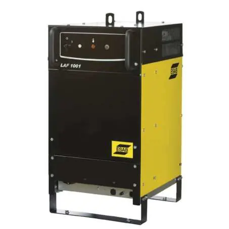
ESAB LAF 1001 / LAF 1001M Welding Power Source
Comprehensive guide for the ESAB LAF 1001 and LAF 1001M welding power sources. Includes installation instructions, electrical connection procedures, operation guidelines, maintenance, and technical specifications.
Table of contents
Manual images
Click an image to enlargeQuick guide from the manual
The ESAB LAF 1001 and LAF 1001M are remote-controlled 3-phase welding power sources designed for mechanised gas metal arc welding (MIG/MAG) or submerged arc welding (SAW). Installation must be performed by a professional. The unit is fan-cooled and features automatic thermal overload protection.
Safety precautions
- Electric Shock: Install and ground the unit according to the manual. Do not touch live electrical parts with bare skin or wet clothing.
- EMF: Welders with pacemakers should consult a physician. Keep electrode and work cables together on the same side of the body.
- Fumes and Gases: Use proper ventilation or extraction at the arc.
- Arc Rays: Use correct welding screens and protective clothing.
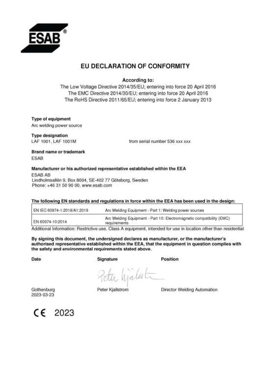
- Class A Equipment: Not intended for use in residential locations where power is provided by the public low-voltage supply system.
Installation and connections
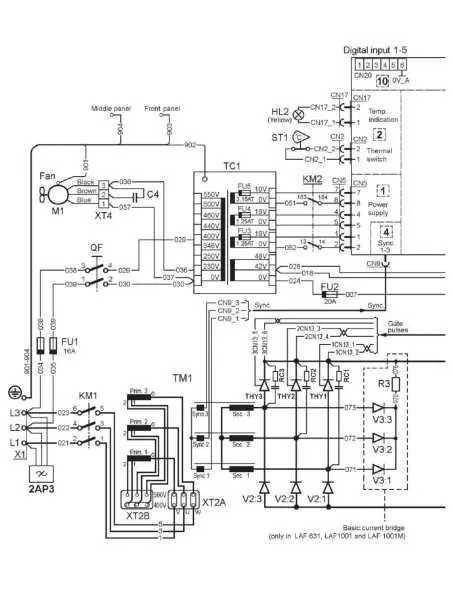
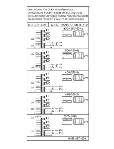
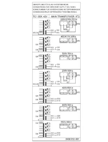
The unit is delivered connected for 400 V. For other supply voltages, the main and control transformer must be reconfigured according to the connection instructions in the manual. This requires removing the side plates.
- Location: Place on a level foundation. Ensure cooling air flow is not obstructed. Secure the equipment if the ground is uneven.
- Mains Connection: Select the correct cable area and fuse based on the tables provided in the manual.
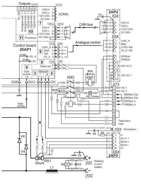
- Control Cable: Connect to the 28-pin connector on the inside of the power source.
- Welding Cables: Connect to the + and - terminals on the front panel.
Operation
The front panel contains the main circuit-breaker (0/1), a white indicator lamp for power, a yellow indicator lamp for overheating, and a pushbutton for resetting the 42 V supply fuse. The power source must be set to analogue mode to use the PEI control unit.
Maintenance
- Cleaning: Clean the welding power source as necessary using dry compressed air. Blocked air inlets or outlets will lead to overheating.
- Contactor: If the contactor requires cleaning, it must be taken apart completely. Never use compressed air on the contactor without disassembling it first.
Technical specifications
- Enclosure Class: IP23 (suitable for indoor and outdoor use).
- Operating Temperature: -10 to +40 °C.
- Weight: 330 kg.
- Duty Cycle: 800 A at 100% duty cycle.
Manufacturer information
ESAB
Practical help
Common problems
Yellow indicator lamp is illuminated
The thermal cutout has deployed due to excess temperature. Wait for the unit to cool down; the lamp will go out automatically.
Unit malfunction
Call for expert assistance. Do not attempt to rectify faults during the warranty period.
Overheating
Check for blocked air inlets or outlets and clean the unit with dry compressed air.
Before use
- Ensure installation is performed by a professional.
- Verify that the mains voltage matches the unit configuration (default 400V).
- Ensure side panels are closed during operation.
- Check that the workplace is free from drafts.
- Wear appropriate personal protective equipment (safety glasses, flame-proof clothing, gloves).
- Ensure the return cable is connected securely.
Images and diagrams
- Wiring diagrams illustrate the internal connections for the main transformer and control board.
- Connection instructions provide specific configurations for different supply voltages (e.g., 230V, 400V, 500V, 550V).
Model compatibility
- Not for residential use (Class A equipment).
- Must be set to analogue mode to use the PEI control unit.

Manual page author
Michael Turner
Technical manual editor
Reviews PDF manuals for structure, safety notes, and practical product details so readers can find the right information quickly.