Automotive / Motorcycle Accessories
User Manual for VEVOR XLLINCMIG 100L MIG Welding Torch
Quick guide for the VEVOR XLLINCMIG 100L MIG Welding Torch. Includes installation steps, safety requirements, maintenance tips, and technical specifications.
Table of contents
Manual images
Click an image to enlargeQuick guide from the manual
The VEVOR XLLINCMIG 100L is a MIG welding torch designed for professional and home use. This manual provides essential instructions for installation, operation, and maintenance to ensure safe and efficient performance. Always ensure the equipment is handled by skilled personnel with appropriate safety knowledge.
Main Parameters
- Model: XLLINCMIG 100L
- Length: 10FT (3.0m)
- Rating Amperage: 100A
- Duty Cycle (CO2 gas): 100%
- Duty Cycle (Mixed gas): 40%
Installation
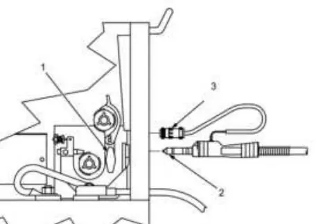
- Gun Securing: Locate the gun securing knob.
- Insertion: Loosen the gun end knob. Insert the gun end into the drive assembly until it bottoms out, then tighten the knob securely.
- Connection: Insert the gun trigger plug into the receptacle and tighten the threaded collar.
- Testing: Press the trigger switch to feed energized wire and start the gas flow.
Operation and Usage
To ensure smooth wire delivery and prevent damage:
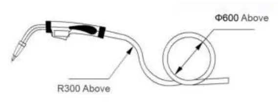
- Cable Handling: Avoid bending the welding gun cable excessively. Keep the cable stretched during use to prevent wire delivery issues.
- Guide Wire Spring: When loading or unloading, keep the guide wire spring straight to prevent permanent deformation and increased feeding resistance.
- Nozzle Adjustment: The guide wire spring naturally extends in the welding gun, with its front end about 5-8mm from the lower end of the distributor. When the conductive nozzle is tightened, the spring can be moderately tightened.
Maintenance
- Cleaning: Periodically purge the guide wire spring with dry compressed air.
- Nozzle Care: Spray or brush spatter off the nozzle mouth to extend its life. Do not use the gun to hit the nozzle to clean spatter.
- Storage: If the welding gun is stopped for more than a week, remove the welding wire to prevent rust and increased resistance in the guide wire spring.
- Handling: Do not use the torch cable to pull the wire feed or the welder.
Safety Requirements
- Read the manual carefully before installation and understand configuration requirements (e.g., protective gas).
- Ensure a skilled person performs the operation.
- Do not overload the torch; the rated current indicates the working limit.
- Do not use cables with insufficient sectional area or damaged insulation.
- Avoid hot working contact between the welding gun and sharp objects.
- Always use a mask and protective equipment.
- When checking wire feed, keep the gun away from eyes, face, and body to avoid injury from flying wire.
Disposal
This product is subject to European Directive 2012/19/EU. The crossed-out wheelie bin symbol indicates that the product requires separate refuse collection and must be taken to a recycling point for electrical and electronic devices.
Manufacturer information
VEVOR
Practical help
Common problems
Wire delivery is not free/smooth
Avoid bending the cable; keep it stretched during use.
Spatter buildup on nozzle
Spray or brush the nozzle mouth; do not hit the nozzle with the gun to clean it.
Rust or high resistance in guide wire spring
Remove the welding wire if the gun is stopped for more than a week.
Before use
- Verify the welding wire feeding machine and protective gas are configured correctly.
- Ensure the cable insulation is intact and not damaged.
- Wear appropriate mask and protective equipment.
- Ensure the gun is connected securely to the drive assembly.
- Check that the trigger plug is fully inserted and the collar is tightened.
Specs in practice
- Rating Amperage
- 100A maximum current capacity.
- Duty Cycle (CO2)
- 100% duty cycle when using CO2 gas.
- Duty Cycle (Mixed)
- 40% duty cycle when using mixed gas.
Images and diagrams
- The installation diagram illustrates the gun securing knob, the insertion point into the drive assembly, and the trigger plug connection.
- The usage diagram shows the recommended bending radius (R300 above) and cable layout (600 above) to ensure smooth wire delivery.
Model compatibility
- Designed for use with compatible MIG welding machines.
- Requires skilled personnel for installation and operation.

Manual page author
Michael Turner
Technical manual editor
Reviews PDF manuals for structure, safety notes, and practical product details so readers can find the right information quickly.