Electronics / Video Transmission
Extron TLP Pro 1225MG, 1525MG, and 1725MG Setup Guide
A comprehensive setup guide for the Extron TLP Pro 1225MG, 1525MG, and 1725MG touch panels. Includes instructions for mounting, cabling, power connection, network configuration, and reset procedures.
Table of contents
Manual images
Click an image to enlargeQuick guide from the manual
This guide provides setup instructions for the Extron TLP Pro 1225MG, 1525MG, and 1725MG touch panels. Before beginning, ensure you have downloaded the necessary software: GUI Designer, Global Configurator, Global Scripter, and Toolbelt. Obtain network information (DHCP status, IP address, subnet mask, gateway) from your network administrator and note the device MAC address from the label on the back.
Mounting
The touch panels can be wall-mounted or rack-mounted.
Wall Mounting
With a wall box:
- Cut a hole in the drywall (9.6 inches wide x 6.6 inches high) and install the Extron BB 700M box.
- Place the metal mounting plate against the wall, mark the four holes, and drill pilot holes.
- Secure the mounting plate with four #10 screws.
- Run and connect cables to the back of the touch panel.
- Insert the two provided #6-32 screws with washers into the mounting screw slot, leaving a gap for the flange.
- Hold the touch panel at a slight angle, lower the notches over the hooks on the mounting plate.
- Swing the bottom of the panel inwards until it lies flat.
- Secure the panel to the mounting plate with the mounting screws.
Without a wall box:
You can mount directly into drywall. Download the cut-out template from www.extron.com, mark the wall, cut the hole (9.25 inches wide x 6.25 inches high), and follow the mounting plate installation steps above.
Rack Mounting
These panels can be mounted in a standard 19-inch equipment rack using optional kits (RM2 for 1225MG, RM3 for 1525MG/1725MG). Refer to the Underwriters Labs Guidelines for Rack Mounting in the full user guide.
Front Panel Features
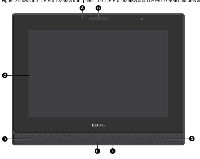
- Ambient light sensor: Monitors light levels and adjusts screen brightness.
- Status light: Programmable LED light bar above the screen.
- Capacitive touch screen: Provides control of AV systems.
- Speakers: Stereo audio for video preview and feedback.
- Motion sensor: Detects motion (3-5 feet away, at least 15 degrees from center) to trigger sleep/wake functions.
- Menu button: Activates the setup menu.
Rear Panel Features
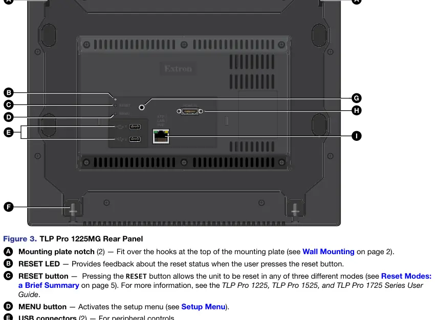
- RESET button: Used for various reset modes.
- RESET LED: Provides feedback during reset operations.
- USB connectors: For peripheral controls.
- Audio output: 3.5 mm line level output.
- HDMI input: For alternative video input.
- XTP/LAN/PoE input: Connects to network or XTP source.
Connecting Power
The TLP Pro 1725MG includes the PI 140 power injector; for 12-inch and 15-inch models, it must be purchased separately.
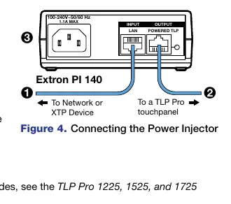
- Connect a straight-through Ethernet cable from the power injector to a switch or router.
- Connect a second straight-through cable from the power injector to the touch panel XTP/LAN/PoE connector.
- Connect the IEC power cord to a 100-240 VAC, 50-60 Hz power source.
Reset Modes
- Use factory firmware: Press and hold the RESET button while applying power.
- Reset All IP Settings: Press and hold the RESET button for 6 seconds. After the LED blinks twice, release and momentarily press the button.
- Reset to Factory Defaults: Press and hold the RESET button for 9 seconds. After the LED blinks three times, release and momentarily press the button.
- Enable/Disable DHCP: Press the RESET button five times consecutively.
Setup Menu
Press the MENU button on the rear or front panel to access the setup menu. Use the navigation bar to access Status, Network, Display, Audio, Input, and Advanced settings.
Official resources from the manual
Manufacturer information
Extron Electronics
Practical help
Common problems
Device will not power on
Ensure the PoE injector is connected correctly and receiving power from a 100-240 VAC source.
Forgotten password
Reset the device to factory defaults. The password will reset to 'extron' for both admin and user accounts.
No network connection
Verify DHCP settings and IP address configuration in the Setup Menu.
Before use
- Download GUI Designer, Global Configurator, Global Scripter, and Toolbelt software from www.extron.com.
- Obtain network details (DHCP status, IP, Subnet, Gateway) from your administrator.
- Note the MAC address from the label on the back of the device.
- Ensure a PoE injector is available (required for 12-inch and 15-inch models).
Specs in practice
- TLP Pro 1225MG
- 12.1 inch screen with 1280x800 resolution.
- TLP Pro 1525MG
- 15.6 inch screen with 1366x768 resolution.
- TLP Pro 1725MG
- 17.3 inch screen with 1920x1080 resolution.
Images and diagrams
- Figure 1: Wall mounting procedure showing the BB 700M box and mounting plate installation.
- Figure 2: Front panel layout identifying sensors, screen, and menu button.
- Figure 3: Rear panel layout showing reset button, ports, and mounting slots.
- Figure 4: Power injector connection diagram.
Model compatibility
- Requires an Extron IP Link Pro control processor on the same Ethernet subnetwork.
- 12-inch and 15-inch models require a separately purchased PoE injector.
- Some XTP models may provide remote power; check the Extron website for your specific XTP model.

Manual page author
Michael Turner
Technical manual editor
Reviews PDF manuals for structure, safety notes, and practical product details so readers can find the right information quickly.