Lighting / Fixtures
Installation and User Guide for FLOS Camouflage Wall Lamp
Comprehensive installation and maintenance guide for the FLOS Camouflage wall lamp (Ø140 and Ø240 models). Includes wiring diagrams, safety instructions, mounting steps, and painting guidelines.
Quick answers from the manual
Quick answer
- The FLOS Camouflage is a wall lamp available in Ø140 and Ø240 versions. Installation must be performed by qualified personnel. The Ø140 model requires a 24V SELV line and a remote power supply, while the Ø240 model operates on 220-240V with an integral power supply. p. 5, 7, 10
Key actions
- Mounting the fixture p. 6, 8, 9
- Wiring the fixture p. 7, 10
- Painting the cover p. 10
Maintenance and reset
- Clean periodically with a soft cloth and neutral soap. Protect screw threads with silicone grease. p. 2
Show 2 more answers Show less
Technical specifications
| Parameter | Value | Meaning | Pages |
|---|---|---|---|
| Camouflage Ø140 | 6.5W/24V | Power consumption and voltage requirement. | p. 5 |
| Camouflage Ø240 | 9.8W/220-240V | Power consumption and voltage requirement. | p. 5 |
Where to find it in the PDF
- Installation Ø240 p. 6
- Wiring Diagrams p. 7
- Installation Ø140 p. 8, 9
Table of contents
Manual images
Click an image to enlargeQuick guide from the manual
The FLOS Camouflage is a wall lamp available in two sizes: Ø140 and Ø240. Installation must be performed by qualified personnel in compliance with national safety regulations. The device requires specific maintenance to ensure longevity, including periodic cleaning and protection of the paint coating. The luminaire is not intended for use with aggressive chemical substances.
Installation
The installation process varies slightly depending on the model and mounting method:
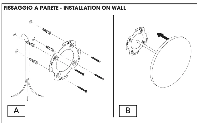
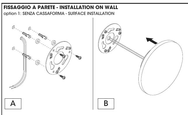
- Surface Installation: Use the provided mounting plate to secure the fixture to the wall. Ensure screws are tightened alternately or crosswise.
- Recessed Box Installation (Ø140 only): An optional recessed box (code F1318000) can be used for a flush-with-the-wall finish.
- Disassembling: To remove the fixture, rotate the cover as indicated in the diagrams.
Wiring
Ensure the power is disconnected before starting any electrical work. The protection rating of the electrical connection must be equal to or greater than the IP rating of the luminaire.
- ON-OFF Wiring: Connect the Brown (L), Blue (N), and Yellow/Green (Ground) wires.
- DALI / 1-10V Wiring: Connect the Brown (L), Blue (N), Yellow/Green (Ground), Violet (D+), and Grey (D-) wires.
- SELV Line: For the Ø140 model, use a 24V SELV line.
Maintenance and Painting
To maintain the fixture:
- Cleaning: Clean periodically using a soft cloth and neutral soap. Do not use aggressive chemical substances (fertilizers, weed killers, lime).
- Protection: It is recommended to apply silicone grease to the threads of the closing screws to facilitate future maintenance.
- Painting: If painting the cover, use only water-based paint. It is recommended to treat the surface with fine-grained sandpaper before applying the color.
Technical Specifications
- Camouflage Ø140: 6.5W/24V, Total power 8W, Class III, MID-POWER LED, Remote electronic power supply (to be ordered separately).
- Camouflage Ø240: 9.8W/220-240V, Total power 12W, Class I, MID-POWER LED, Integral electronic power supply.
- Protection: IP65 (dust-tight and protected against water jets). Impact protection: IK08 (Ø240) / IK10 (Ø140).
Manufacturer information
FLOS
Practical help
Common problems
Corrosion on the fixture
Ensure the paint coating is not damaged during installation. Avoid contact with aggressive chemicals like fertilizers or lime.
Difficulty unscrewing the fixture for maintenance
Apply silicone grease to the threads of the closing screws before exposing the fixture to weather conditions.
Before use
- Ensure power is disconnected before starting installation.
- Verify that the electrical connection IP rating is equal to or greater than the luminaire's IP rating.
- Ensure installation is performed by qualified personnel.
- For Ø140, ensure a 24V SELV line is used.
- Check that the junction box and terminal block (not supplied) are suitable for the installation.
Show more Show less
Images and diagrams
- Wiring diagrams show connections for both standard ON-OFF and DALI/1-10V control systems.
- Installation diagrams illustrate the mounting plate attachment and the rotation mechanism for securing the cover.
Model compatibility
- Ø140 requires a remote electronic power supply (to be ordered separately).
- Ø240 includes an integral electronic power supply.
- Optional recessed box (F1318000) available for Ø140.

Manual page author
Michael Turner
Technical manual editor