Toys / Games
User Manual for FMS 1220mm Ranger RC Aircraft
Quick guide for the FMS 1220mm Ranger, covering assembly, Reflex flight stabilization system setup, battery installation, preflight checks, and troubleshooting.
Table of contents
Quick guide from the manual
The FMS 1220mm Ranger is a high-wing RC aircraft featuring the Reflex flight stabilization system. This manual provides essential instructions for assembly, setup, and safe operation. Always perform a ground range test before the first flight and ensure all screws are tightened.
Reflex system overview
The Reflex system includes three flight modes: Stabilized, Optimized, and Off. It automatically recognizes SBUS/PPM/PWM systems. The flight controller operates in stabilized mode by default.
- Stabilized mode: Levels the aircraft when control sticks are released.
- Optimized mode: Maintains attitude by counteracting inflight upsets.
- OFF: Disables all gyro functionality for manual flight.
Operation: Turn on the transmitter first, then the receiver. Keep the aircraft level on a flat surface until the flight controller calibrates (aileron and elevator servos will cycle 3 times).
Model assembly
The Ranger features a screw-together design. Assembly steps include:
- Landing gear: Invert the fuselage and secure the landing gear assembly with the provided screws.
- Horizontal stabilizer: Insert into the slot at the rear of the fuselage and secure with screws.
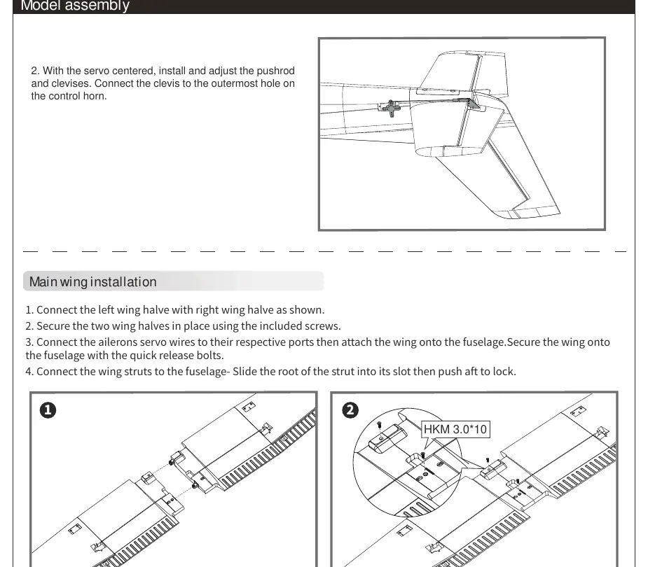
- Main wing: Connect wing halves, attach to the fuselage using quick-release bolts, and slide wing struts into place.
- Floats: If using for water operations, connect float struts to the fuselage and secure the water rudder servo cable.
- Propeller: Assemble the spinner and propeller, ensuring the motor rotates clockwise when viewed from the rear.
Battery installation
Use a 3S 1300mAh 25C Li-Po battery. Apply hook tape to the cable end, slide the battery into the hatch with the cable facing the rear, and secure it. Adjust the battery position to achieve the correct Center of Gravity (CG).
Safety and maintenance
Always handle Li-Po batteries with caution. Never charge unattended, never discharge below 3V, and store at room temperature. For repairs, use foam-safe adhesives. Regularly check all screws and ensure the spinner is firmly attached before every flight.
Troubleshooting
If the aircraft does not respond to throttle, ensure the ESC is armed and the throttle channel is not reversed. If the motor loses power or pulses, the ESC may have triggered the Low Voltage Cutoff (LVC); land immediately and recharge the battery.
Manufacturer information
FMS Model
Practical help
Common problems
Aircraft will not respond to throttle but responds to other controls.
Ensure the ESC is armed by lowering the throttle stick and trim to the lowest settings. Check if the throttle channel is reversed on the transmitter.
Motor loses power or pulses.
The ESC may have triggered the Low Voltage Cutoff (LVC). Land immediately and recharge the flight battery.
Extra propeller noise or vibration.
Check for damaged parts, loose spinner/propeller, or if the propeller is installed backward.
LED on receiver flashes slowly.
Indicates power loss to the receiver. Check connections between the ESC and receiver, and check for servo damage or binding.
Before use
- Ensure transmitter and receiver are bound.
- Check that all control sticks are in neutral and throttle is OFF.
- Perform a ground range test with an assistant.
- Verify all servo wires are securely connected.
- Ensure the battery is fully charged and securely installed.
- Confirm the Center of Gravity (CG) is 50-60mm from the leading edge of the main wing.
Specs in practice
- Recommended Battery
- 3S 1300mAh 25C Li-Po
- Center of Gravity (CG)
- 50-60mm from the leading edge of the main wing
Images and diagrams
- The receiver diagram shows the correct channel order: 1-Aileron, 2-Elevator, 3-Throttle, 4-Rudder, 5-Gear, 6-Spare.
- Clevis installation: Pull the tube, spread the clevis, insert the pin into the control horn, and slide the tube back to lock.
Model compatibility
- Compatible with all radio systems with 4 channels or above.
- Reflex system is pre-programmed for this specific aircraft; no further programming is needed.

Manual page author
David Miller
Documentation analyst
Organizes user manual content into clear summaries, with attention to model details, product context, and everyday usability.