Plumbing / Sump Pumps
User Manual for Little Giant 6EC & 10EC Series Sump Pumps
Quick guide for the Little Giant 6EC & 10EC Series Sump Pumps. Includes installation steps, electrical connection diagrams, maintenance procedures, and troubleshooting tips.
Table of contents
Manual images
Click an image to enlargeQuick Guide from the Manual
The Little Giant 6EC and 10EC series are submersible sump pumps designed for use in basins or lift stations. They are suitable for pumping clear water or effluent gray water containing semi-solids up to 1/2 inch in diameter. Do not use these pumps for sewage, abrasive materials, or corrosive liquids.
Safety Instructions
DANGER: Risk of death, personal injury, or property damage due to explosion, fire, or electric shock. Do not use to pump flammable or explosive fluids. Do not handle the pump with wet hands or while standing on wet surfaces.
WARNING: High voltages are present. Always disconnect power before servicing. Use a properly grounded receptacle. Do not use an extension cord.
NOTICE: Do not run the pump dry. This can cause overheating, damage the seals, and void the warranty. The pump is not suitable for pond applications.
Installation
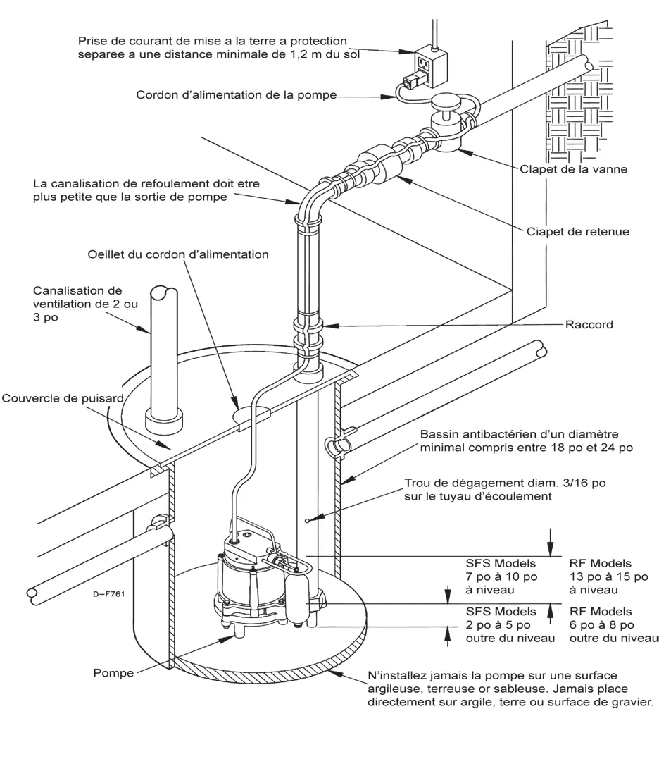
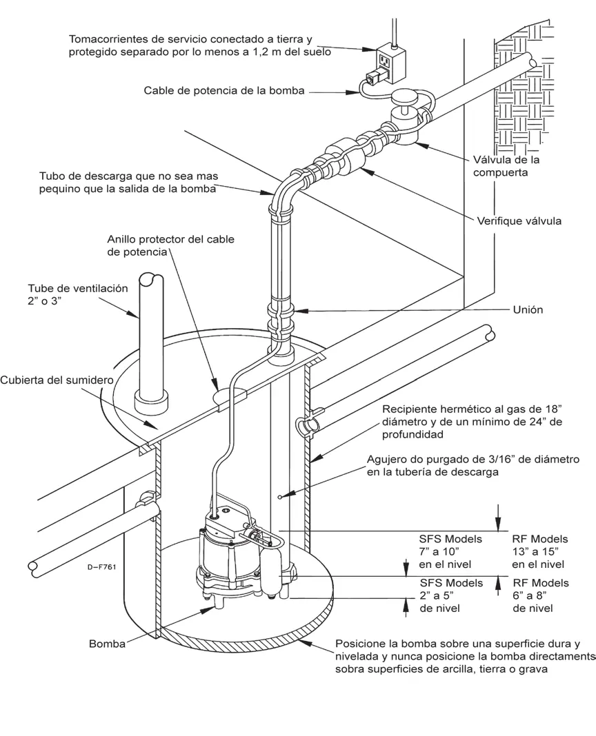
The pump must be installed in a gas-tight basin at least 18 inches in diameter and 24 inches deep. Place the pump on a hard, level surface; never place it directly on clay, earth, or gravel. Connect the discharge piping using pipe joint compound. A check valve must be used in the discharge line to prevent backflow. Drill a 1/8 inch or 3/16 inch relief hole in the discharge pipe below the floor line to prevent air locking.
Electrical Connections
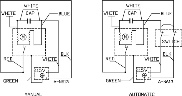
Check the pump label for the correct voltage. A ground fault circuit interrupter (GFCI) is required. The pump should be connected to its own dedicated circuit. Do not modify the power cord or remove the grounding prong.
Operation Testing
Before automatic operation, ensure the gate valve in the discharge line is open. Run water into the basin until the pump activates. Confirm that the pump and switch function correctly, and that there are no leaks in the discharge plumbing. It is normal for a stream of water to spray from the air bleed hole in the pump's plumbing; ensure this spray is captured within the basin.
Maintenance
Inspect and test the pump system every three months. Let the pump cool for at least 2 hours before servicing, as the oil inside can become hot and pressurized. Check power cords for damage or corrosion. Remove debris from the basin and ensure the impeller turns freely. Do not open the sealed motor housing or remove the impeller, as this will void the warranty.
Troubleshooting
If the pump does not turn on, check if it is plugged in, check the circuit breaker, or inspect the float for obstructions. If the pump will not shut off, check for float obstructions or an air lock. If the pump runs but does not discharge, ensure the check valve is installed correctly and not stuck. If the pump cycles continuously, install a check valve or a larger basin.
Replacement Parts
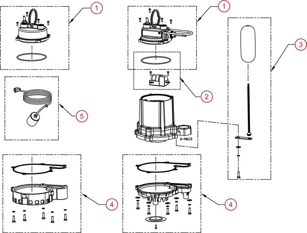
Replacement parts include cover assemblies (115V/230V, automatic/manual), capacitor kits, float assemblies, and volute bases. Refer to the replacement parts diagram for specific part numbers.
Practical help
Common problems
Pump does not turn on
Check if the pump is plugged in, reset the circuit breaker, clean the float, or check for float obstructions.
Pump will not shut off
Check for float or float rod obstructions, remove pump to clean the air bleed hole, or replace a defective switch.
Pump runs but does not discharge liquid
Ensure the check valve is installed in the correct direction, remove and clean the check valve, or clean the pump inlet.
Pump cycles continuously
Install a check valve in the discharge line, inspect the check valve for leaks, or install a larger basin.
Before use
- Ensure the basin is at least 18 inches in diameter and 24 inches deep.
- Place the pump on a hard, level surface (not clay, earth, or gravel).
- Verify the power outlet is a GFCI-protected circuit.
- Install a check valve in the discharge line.
- Drill a 1/8 inch or 3/16 inch relief hole in the discharge pipe.
- Ensure the gate valve is open before testing.
Specs in practice
- Air Bleed Hole
- Essential to prevent air lock; water spraying from this hole is normal.
Images and diagrams
- Wiring diagrams show the connections for manual and automatic operation.
- Typical installation diagram illustrates the basin, vent pipe, check valve, and gate valve configuration.
Model compatibility
- Designed for water only.
- Suitable for clear water or effluent gray water with up to 1/2 inch semi-solids.
- Not suitable for sewage, abrasives, or corrosive liquids.

Manual page author
David Miller
Documentation analyst
Organizes user manual content into clear summaries, with attention to model details, product context, and everyday usability.