Plumbing / Sump Pumps
User Manual for Zoeller AquaNot 508 Fit 12V DC Battery Backup Pump
Quick guide for the Zoeller AquaNot 508 Fit 12V DC Battery Backup Pump. Includes installation steps, wiring diagrams, Z Control WiFi setup, maintenance, and troubleshooting.
Table of contents
Manual images
Click an image to enlargeQuick Guide from the Manual
The Zoeller AquaNot 508 Fit is a 12V DC battery backup pump designed to protect against flooding during power outages or primary pump failure. Key features include self-testing, smart diagnostics, and Z Control Cloud connectivity. Important: The system requires a 12V deep-cycle battery (not included) and must be installed with the DC pump intake above the primary pump intake to prevent airlocks.
Product Description
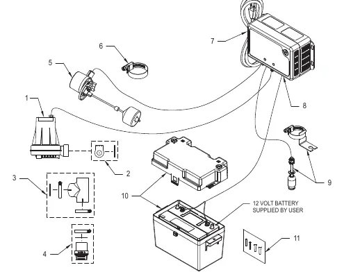
The system includes a DC pump, a smart controller, and a battery box. It is designed for clear water pumping. The controller features built-in WiFi for remote monitoring via the Z Control Cloud, allowing for alerts and status updates.
Installation
Preparation: Ensure the primary pump and controller are on separate circuits. The controller must be within 8' of a 115V outlet and 6' of the pump/basin.
- Disconnect power to the primary pump.
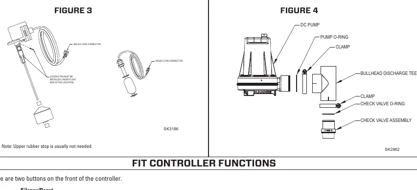
- Install the check valve assembly into the primary pump discharge.
- Secure the discharge tee onto the check valve using a hose clamp.
- Slide the DC pump into the fitting and tighten the hose clamp.
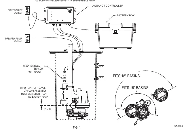
- Assemble the operational float switch and high water switch using the provided clamps. Ensure the "off" level of the float is at least 1" above the DC pump outlet.
- Install the Fit Controller using the provided anchors, at least 3' above the sump.
- Connect the controller leads to the battery terminals (Positive to positive, Negative to negative).
- Connect the DC pump plug to the controller.
- Plug the controller into a 115V outlet and reconnect power to the primary pump.
Initial Start-up and Operation
Before leaving the site, perform a test:
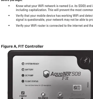
- Plug in the unit; all lights will flash and the alarm will sound to verify functionality.
- Lift the operational float switch to trigger the pump. The alarm will sound after 1 second.
- Press the Silence button to silence the alarm.
- Hold the Silence button for 3 seconds to reset the controller to standby mode.
Connecting to Z Control
The Fit controller can connect to WiFi for remote monitoring:
- Download the Z Control app or use a browser to connect directly to the Fit's SSID (ZCTL_Fit_xxxx).
- If connecting directly, type 192.168.125.1 in your browser address bar.
- Use the WiFi Scan button to select your network and enter the passphrase.
- Once connected, the Z Control LED will turn solid.
Maintenance
Inspect and test the system every 3 months:
- Unplug the primary pump and controller.
- Fill the sump to the "on" level and allow the DC pump to run for a few minutes.
- Press the Silence/Reset button to stop the alarm.
- Reconnect power and ensure the battery light turns yellow (charging) then green.
Troubleshooting
- Pump won't run: Check connections, 30A fuse, battery charge, and for obstructions in the impeller.
- Pump runs but moves little water: Check for airlocks, low battery, or blocked discharge piping.
- Pump cycles too frequently: Adjust the rubber stops on the float rod.
- Alarm sounds during recharge: Unplug the charger, check the battery, and reconnect.
Practical help
Common problems
Pump won't run
Check all wire connections, the 30A fuse on the controller, battery charge, and ensure there are no obstructions in the pump impeller.
Pump runs but moves little or no water
Check for airlocks (ensure weep hole is clear), low battery, or blocked discharge piping.
Pump cycles too frequently
Adjust the positions of the rubber stops on the operational float rod.
Alarm sounds during battery recharge
Unplug the charger from the 115V outlet, disconnect the black lead from the battery, check the battery, and reconnect.
Before use
- Inspect pump for shipping damage.
- Ensure a properly grounded 115V receptacle is available.
- Verify primary pump and controller are on separate circuits.
- Ensure battery is a 12V deep-cycle type (90+ amp-hour recommended).
- Verify DC pump intake is set above the primary pump intake.
- Ensure discharge piping is 1-1/2" SCH 40 PVC.
Specs in practice
- 35 GPM at 10'
- Flow rate of 35 gallons per minute at 10 feet of head pressure.
- Duty Cycle 10%
- The system is capable of 2 days of operation at this duty cycle.
Images and diagrams
- Exploded View: Shows the assembly of the pump, check valve, and float switches.
- Installation Diagram: Illustrates the correct positioning of the pump and float switches in the sump basin.
- Float Switch Diagram: Details the connection and positioning of the operational and high-water floats.
Model compatibility
- Requires 12V deep-cycle battery (not included).
- Not for use in septic tanks or sewage pits.
- Requires 2.4GHz WiFi network for Z Control connectivity.
- Not compatible with WEP or Open WiFi networks.

Manual page author
Michael Turner
Technical manual editor
Reviews PDF manuals for structure, safety notes, and practical product details so readers can find the right information quickly.