Plumbing / Sump Pumps
Zoeller 155922-E 12 Volt DC Battery Backup Pump Installation Instructions
Comprehensive installation and operation guide for the Zoeller 155922-E 12 Volt DC Battery Backup Pump. Includes wiring diagrams, maintenance steps, troubleshooting, and battery selection advice.
Table of contents
Manual images
Click an image to enlargeQuick Guide from the Manual
The Zoeller 155922-E is a 12V DC battery backup pump designed to protect against flooding during power outages or primary pump failure. Key requirements for installation include a 115V grounded receptacle, a deep-cycle 12V marine battery (90+ amp-hour), and 1-1/2 inch SCH 40 PVC discharge piping. The system is self-testing and features smart diagnostics to prevent air locks and dry running.
System Description
This backup system is designed for clear water pumping. It includes a controller with smart diagnostics, a DC pump, and float switches. The controller automatically charges and maintains the battery. It is capable of distinguishing between air and water to purge air locks and prevent continuous dry running.
Installation
Pre-installation: Ensure the primary pump and controller are on separate circuits. The controller must be within 8' of a 115V outlet and 6' of the pump/basin.
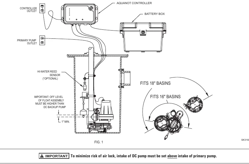
Plumbing: Install the check valve assembly into the primary pump discharge. Use the provided tee fitting and secure with hose clamps. Ensure the intake of the DC pump is set above the intake of the primary pump to minimize air lock risks.
Float Switches: Install the operational float switch above the 'on' level of the primary pump. If using the optional high water float, install it so its 'on' point is higher than the operational float.
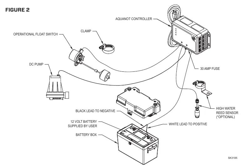
Electrical: Connect the controller to the battery terminals (Positive to positive, Black negative to negative). Plug the controller into a 115V outlet. Do not use an extension cord.
Initial Start-up and Operation
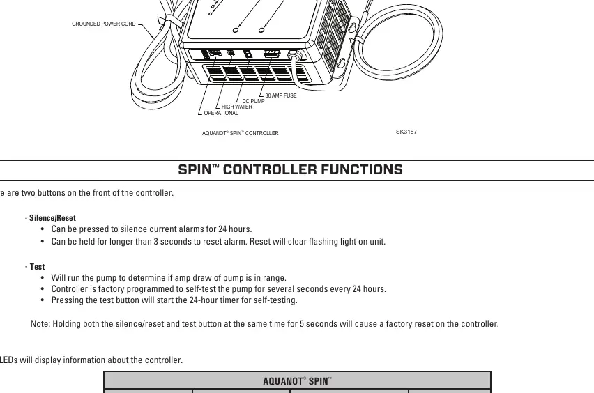
Upon initial power-up, all lights will flash and an alarm will sound to verify functionality. To test the system, lift the operational float switch; the pump should run after a 1-second delay. The system can be reset by holding the Silence button for 3 seconds. The controller features LED indicators for System Ready, Battery status, DC pump status, and Float status.
Maintenance and Troubleshooting
Inspect and test the system at least every 3 months. If the pump fails to run, check connections, the 30-amp fuse, and battery charge. If the pump runs but pumps little or no water, check for airlocks or blocked piping. If the alarm sounds during the recharge cycle, disconnect the battery and check its condition.
Battery Selection
Use a B.C.I. size 27 deep-cycle battery (175-minute reserve capacity or larger). Do not use gel or automotive batteries. Replace the battery every 3 years and keep terminals free of corrosion. For wet cell batteries, check electrolyte levels monthly.
Practical help
Common problems
DC pump won't run
Check for proper connections, clean wire terminal points, check battery charge, and inspect the 30-amp fuse on the controller.
Pump runs but pumps little or no water
Check for airlocks (baffle incoming water), ensure the pump weep hole is clear, and verify discharge piping is not blocked.
Alarm sounds during battery recharge cycle
Unplug the charger from the 115V outlet, disconnect the black lead from the negative battery post, check the battery, and replace if necessary.
Pump cycles too frequently
Check the position of the rubber stops on the operational float rod and adjust the upper rubber float stop as needed.
Before use
- Inspect pump for shipping damage.
- Ensure a properly grounded 115V receptacle is available.
- Verify primary pump and controller are on separate circuits.
- Ensure battery is a deep-cycle 12V marine battery (90+ amp-hour).
- Verify discharge piping is 1-1/2 inch SCH 40 PVC.
- Ensure the DC pump intake is set above the primary pump intake.
Specs in practice
- Power Requirement
- 115V 15 amp circuit.
- Charger Output
- 3 amp multi-stage.
Images and diagrams
- Figure 1 illustrates the in-line installation of the DC pump with the primary pump.
- Figure 2 provides an exploded view of the DC pump and controller components.
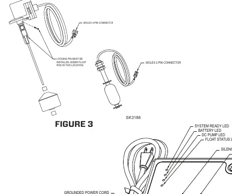
- Figure 3 details the float switch assembly and connections.
- Figure 4 shows the controller connections and LED indicator panel.
Model compatibility
- For indoor use only.
- Do not use in septic tanks or sewage pits.
- Do not use gel batteries or automotive batteries.
- Not for use in swimming pools or marine areas.

Manual page author
David Miller
Documentation analyst
Organizes user manual content into clear summaries, with attention to model details, product context, and everyday usability.