Plumbing / Sump Pumps
User Manual for Zoeller Aquanot 508 Spin 12V DC Battery Backup Pump
Quick guide for the Zoeller Aquanot 508 Spin 12V DC Battery Backup Pump. Includes installation steps, wiring diagrams, controller operation, maintenance, and troubleshooting.
Table of contents
Manual images
Click an image to enlargeQuick guide from the manual
The Zoeller Aquanot 508 Spin is a self-testing 12V DC battery backup sump pump system designed to protect against flooding during power outages or primary pump failure. Before installation, ensure you have a 115V grounded receptacle available and that the primary pump and controller are on separate circuits. The system requires a 12V deep-cycle marine battery (100+ amp hour recommended). Do not use gel or automotive batteries.
Product Description
This system features smart diagnostics and self-testing capabilities. It is designed to purge air and remedy air lock situations automatically. The controller monitors the battery, pump status, and float switches. It includes a multi-stage charger to maintain battery health.
Installation
Pre-installation: Ensure the discharge piping is 1-1/2 inch SCH 40 PVC. Disconnect power to the primary pump before starting.
- Remove all parts from the shipping carton.
- Select a location for the battery and controller within 8' of a 115V outlet and 6' of the pump.
- Install the check valve assembly into the primary pump discharge.
- Secure the discharge tee onto the check valve using a hose clamp.
- Install the operational float switch above the "on" level of the primary pump using the provided clamp. Ensure the float moves freely.
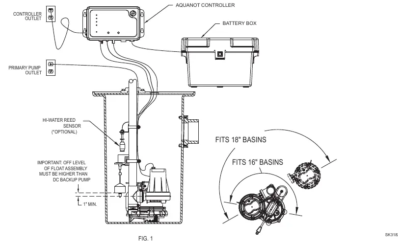
- Install the optional high water switch with the "on" level at least 1" above the operational float.
- Mount the Spin controller using the provided anchors, at least 3' above the sump.
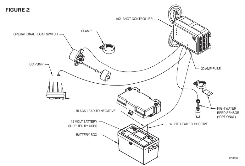
- Connect the DC pump plug to the controller.
- Connect the battery leads: Positive (+) to the positive terminal, black negative (-) to the negative terminal.
- Plug the controller into the 115V wall outlet.
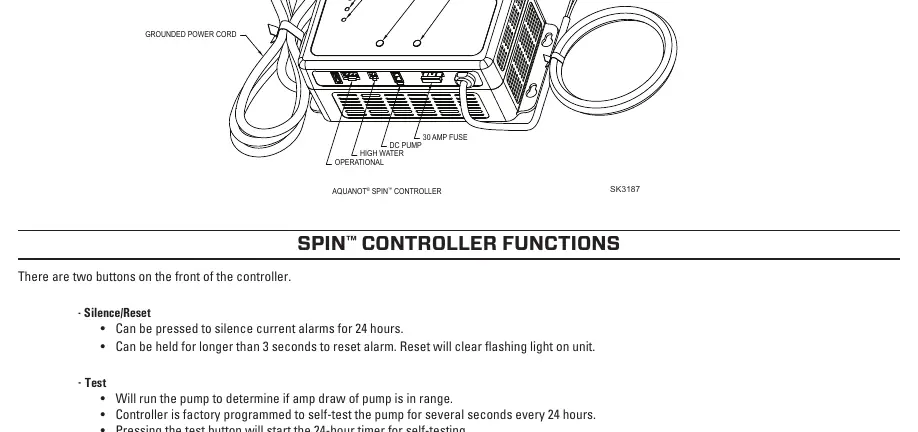
Initial Start-up and Operation
When first plugged in, all lights will flash and the alarm will sound to verify functionality. The system expects the operational switch to be connected. If not, alarms will sound. To reset, hold the Silence button for 3 seconds.
Testing: Run water into the sump to test the installation. The DC pump should activate. If the pump runs but does not pump water, the controller will attempt to purge air. The yellow DC Pump LED will remain on if the pump successfully pumped water.
Maintenance
Inspect and test the system every 3 months:
- Unplug the primary pump and controller.
- Fill the sump with water to the "on" level and allow the pump to run.
- Verify the alarm sounds after 1 second.
- Push the Silence/Reset button to stop the alarm.
- Reset the controller by holding the Silence/Reset button for 3 seconds.
- Plug the units back into the wall outlet.
Troubleshooting
- Pump won't run: Check connections, battery charge, and the 30A fuse on the controller.
- Pump runs but pumps little/no water: Check for airlock, clear the weep hole, and ensure discharge piping is not blocked.
- Pump cycles too frequently: Adjust the rubber stops on the operational float rod.
- Alarm sounds during recharge: Unplug the charger, check the battery, and reconnect.
Battery Selection
Use a B.C.I. size 27 deep-cycle battery with 175-minute reserve capacity or larger. Replace the battery every 3 years. Do not let corrosion build up on terminals. For wet cell batteries, check electrolyte levels monthly.
Practical help
Common problems
Pump won't run
Check all wire terminal connections, verify battery charge, and inspect the 30A fuse on the controller. Replace fuse if blown.
Pump runs but pumps little or no water
Check for airlock (baffle incoming water), ensure the pump weep hole is clear, and verify discharge piping is not blocked.
Pump cycles too frequently
Check the position of the rubber stops on the operational float rod and adjust the upper stop as needed.
Alarm sounds during battery recharge
Unplug the charger from the wall, disconnect the black lead from the negative battery post, check the battery, and reconnect.
Before use
- Ensure a properly grounded 115V receptacle is available.
- Verify the primary pump and controller are on separate circuits.
- Confirm the controller is within 8' of the outlet and 6' of the pump.
- Ensure discharge piping is 1-1/2 inch SCH 40 PVC.
- Test float switch movement to ensure no obstructions.
- Verify battery terminals are clean and tight.
Specs in practice
- Continuous Running Time
- 5.5 hours with recommended battery.
- Power Requirement
- 115V 15 amp circuit.
- Charger Output
- 3 amp multi-stage.
Images and diagrams
- Figure 1: Installation layout showing pump, controller, and float switch placement.
- Figure 2: Exploded view of DC pump components.
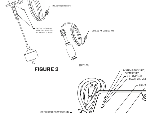
- Figure 3: Float switch assembly and connections.
- Figure 4: Controller interface and wiring connections.
Model compatibility
- Requires 12V deep-cycle marine battery (100+ amp hour recommended).
- Do not use gel or automotive batteries.
- For indoor use only.
- Not for use in septic tanks or sewage pits.

Manual page author
Emily Carter
User documentation editor
Prepares concise manual descriptions and highlights the most useful setup, operation, and maintenance information for readers.