Home / Pet Supplies
Fudajo 64238 125cm Cat Tree User Manual
Quick guide for assembling the Fudajo 125cm Cat Tree (model 64238). Includes part list, hardware identification, and step-by-step installation instructions.
Table of contents
Manual images
Click an image to enlargeImportant Information
This manual provides the necessary steps to assemble the Fudajo 125cm Cat Tree. Before beginning assembly, please verify that all parts listed in the part list are present. Ensure you have a clear, flat space to work on. Use the provided Allen key (E) for tightening all screws. Periodically check the stability of the cat tree and tighten screws if they become loose over time.
Part List
The package includes the following components and hardware:
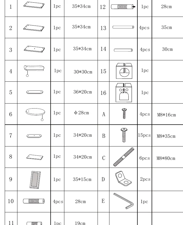
- Components: 16 numbered parts (1-16) including platforms, scratching posts, and house sections.
- Hardware: Screws (A, B, C), L-brackets (D), and Allen key (E).
Please refer to the part list diagram on page 1 to identify each component by its number and dimensions before starting the assembly.
Assembly Instructions
Follow these steps to assemble your cat tree:
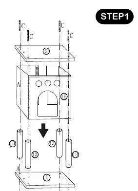
Step 1
Assemble the base and the lower house section. Connect the base (1) to the house (15) using the provided screws and posts (13) as indicated in the diagram.
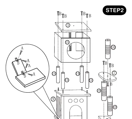
Step 2
Attach the upper platforms and additional scratching posts. Secure the house roof (3) and connect the posts (10, 14) and platforms (7, 9) using screws (B, C).
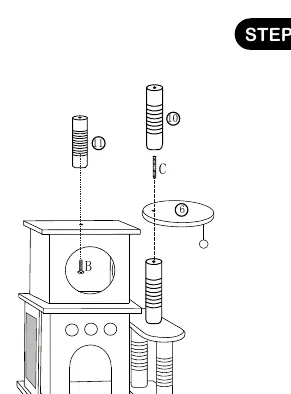
Step 3
Install the upper scratching posts (10, 11) and the top platform (6). Ensure all connections are tightened securely using the provided hardware.
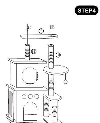
Step 4
Attach the remaining platform (5) and secure it to the top of the structure using screws (B, C).
Step 5
Finalize the assembly by attaching the top-most platform (4) and the hanging toy (12) to the top post.
Practical help
Common problems
Unstable or wobbly structure
Ensure all screws are fully tightened. Check that the base is on a level surface.
Missing parts
Verify all items against the Part List on page 1. If parts are missing, contact the retailer.
Before use
- Unpack all components and lay them out on a flat surface.
- Verify all 16 parts and hardware (A-E) are present.
- Ensure you have the provided Allen key (E).
- Check that the assembly area is clear of obstacles.
- Tighten all screws firmly during assembly.
Images and diagrams
- Page 1 shows an exploded view of all parts with dimensions.
- Page 2 illustrates the 5-step assembly sequence.

Manual page author
David Miller
Documentation analyst
Organizes user manual content into clear summaries, with attention to model details, product context, and everyday usability.