Electronics / Marine Navigation
Installation Instructions for Garmin GPSMAP 12X2 PLUS Chartplotter
Complete installation guide for the Garmin GPSMAP 12X2 PLUS chartplotter. Includes detailed mounting instructions, wiring diagrams for NMEA 0183, NMEA 2000, and J1939 networks, as well as technical specifications and safety guidelines.
Table of contents
Manual images
Click an image to enlargeImportant Information from the Manual
This document provides installation instructions for the Garmin GPSMAP 12X2 PLUS chartplotter. Before beginning, ensure you have the necessary tools: a drill with appropriate bits, a #2 Phillips screwdriver, a jigsaw or rotary tool, file, sandpaper, and marine sealant. Always disconnect the vessel's power supply before starting installation to avoid personal injury or damage to the device.
Mounting Considerations
When selecting a mounting location, consider the following:
- The location should provide optimal viewing and easy access to interfaces.
- The surface must be strong enough to support the device and protect it from vibration or shock.
- Ensure there is room for cable routing and connection.
- The device should not be installed closer to a magnetic compass than the specified compass-safe distance (65 cm).
- The location should be at a vertical angle, not a flat horizontal surface.
Bail Mounting the Device
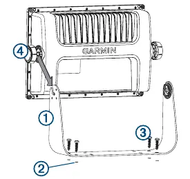
- Use the bail mount bracket as a template to mark the location of the four pilot holes.
- Drill the pilot holes using a bit appropriate for your mounting hardware.
- Secure the bail mount bracket to the surface.
- Install the bail mount knobs on the sides of the device.
- Place the device in the bracket and tighten the knobs.
Flush Mounting the Device
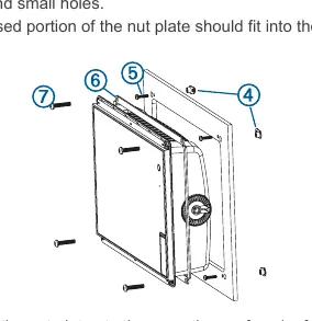
- Trim the included template and secure it to the mounting location.
- Drill one or more holes inside the corners of the solid line on the template to prepare for cutting.
- Use a jigsaw or rotary tool to cut along the inside line.
- Test the fit of the device in the cutout and refine with a file or sandpaper if necessary.
- If using a nut plate, drill the required holes and secure the nut plates to the back of the mounting surface.
- Install the foam gasket on the back of the device.
- Connect all necessary cables before placing the device into the cutout.
- Apply marine sealant between the mounting surface and the device to prevent leakage.
- Secure the device to the mounting surface using the appropriate machine screws.
Wiring and Connections
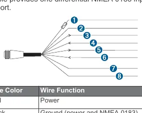
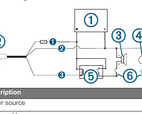
Power/NMEA 0183 Cable: The wiring harness connects the device to power, NMEA 0183 devices, and optional alarms. Do not remove the in-line fuse holder. Connect the red wire to the positive (+) battery terminal and the black wire to the negative (-) battery terminal.
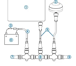
Garmin Marine Network: Use a Garmin Marine Network cable for all connections. Do not use third-party CAT5 cables. If connecting third-party devices like a FLIR camera, a Garmin Marine Network PoE Isolation Coupler (010-10580-10) is required.
NMEA 2000: Connect the device to an existing NMEA 2000 network using the included cables. If no network exists, you can create a basic one using Garmin cables. Use a NMEA 2000 Power Isolator if the network manufacturer is unknown.
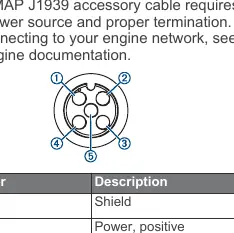
J1939 Engine Network: Use a Garmin GPSMAP J1939 accessory cable. The device can receive J1939 sentences but cannot transmit over this network.
Video Connections: The device supports HDMI Out for screen duplication and CVBS IN for composite video input. Use Garmin accessory cables to prevent corrosion.
Specifications
- Dimensions: 33.0 x 22.6 x 7.9 cm
- Weight: 2.72 kg
- Water Rating: IEC 60529 IPX7 (withstands incidental exposure to water of up to 1 m for up to 30 min)
- Input Voltage: 10 to 32 Vdc
- Fuse: 6 A, 125 V fast-acting
- Temperature Range: -15° to 55°C
Manufacturer information
Garmin Ltd.
Practical help
Common problems
Device not turning off or software inoperable
Ensure third-party devices are not connected directly to the Garmin Marine Network without a PoE Isolation Coupler.
Interference with magnetic compass
Install the device at least the minimum compass-safe distance away (65 cm).
Corrosion of metal contacts
Cover unused connectors with the attached weather caps.
Before use
- Verify mounting location is not exposed to extreme temperatures.
- Ensure the location is strong enough to support the device weight.
- Check for clearance behind the mounting surface for cables.
- Disconnect the vessel's power supply before beginning installation.
- Wear safety goggles and dust mask when drilling or cutting.
Specs in practice
- Water rating: IPX7
- Withstands incidental exposure to water of up to 1 meter for up to 30 minutes.
- Compass-safe distance: 65 cm
- Minimum distance from a magnetic compass to prevent interference.
- Input voltage: 10 to 32 Vdc
- Operating voltage range for the device.
Images and diagrams
- Bail mount: Shows the bracket as a template for marking pilot holes.
- Flush mount: Illustrates the template usage, cutting, and nut plate installation.
- Wiring harness: Details the color-coded connections for power, NMEA 0183, and alarm.
Model compatibility
- Compatible with NMEA 2000 networks.
- Supports J1939 engine networks (receive only).
- Supports NMEA 0183 devices (one Tx and one Rx port).

Manual page author
Emily Carter
User documentation editor
Prepares concise manual descriptions and highlights the most useful setup, operation, and maintenance information for readers.