Sports / Marine Equipment
Installation Guide for Garmin GC 200 Marine IP Camera
Quick installation guide for the Garmin GC 200 Marine IP Camera. Learn how to mount the camera, connect power, understand LED status indicators, and review technical specifications.
Table of contents
Manual images
Click an image to enlargeQuick guide from the manual
This document provides installation instructions for the Garmin GC 200 Marine IP Camera. Before beginning, ensure you have a drill with a 2 mm (1/16 in.) drill bit and a Pozidriv screwdriver. Always test the camera in the selected location before permanent mounting. Note that you must update your chartplotter software to set up and view the camera feed.
Mounting the Camera
The camera can be mounted upside-down or sideways, and the image can be reversed in the chartplotter settings. Follow these steps for installation:
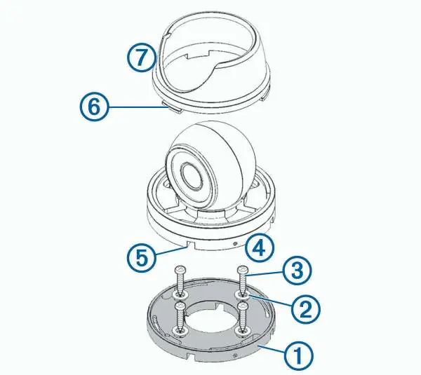
- Secure the template to the mounting location.
- Drill pilot holes using a 2 mm (1/16 in.) drill bit.
- Use the included hex wrench to loosen the screw on the side of the camera base and remove the base from the camera body.
- Feed the camera cables through the base or one of the cable channels.
- Align the base with the pilot holes and secure it using the provided washers and screws.
- Attach the camera to the base and tighten the screw.
- Connect the camera cables.
- Align the slots on the camera base with the collar lugs and turn the collar until it locks.
Connection Considerations
The camera requires specific power configurations depending on your system:
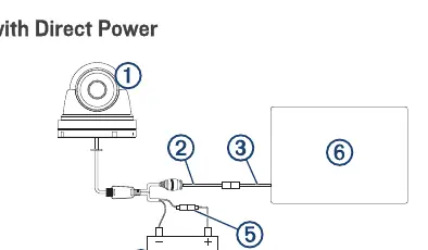
- Direct Power: Connect to a 9 to 18 Vdc power source. You must install a 1 A fast-acting fuse on the power wire.
- 24 Vdc Systems: Do not connect directly to a 24 Vdc system. You must use a Garmin Power Module to avoid permanent damage.
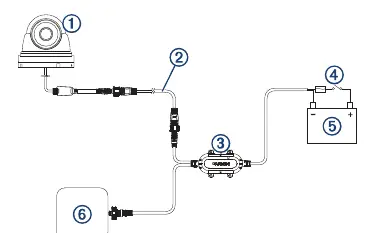
- Garmin Power Module: Using the power module (010-12527-00) allows for a single camera cable connection, which is beneficial for long distances (e.g., on a mast).
Camera Status LED
The LED on the camera indicates its current state:
- Solid red: The camera is on.
- Solid green: The camera is connected to the network and transmitting data.
- Flashing green: The camera detects motion.
Specifications
- Dimensions (Base): 87 x 79 mm (3.4 x 3.1 in.)
- Weight: 520 g (1.2 lbs.)
- Water rating: IEC 60529 IPX7 (withstands incidental exposure to water up to 1 m for 30 min)
- Operating temperature: -20 to 60°C (-4 to 140°F)
- Input voltage: 9 to 18 Vdc (direct) or 9 to 32 Vdc (with Power Module)
- Power consumption: Max 5 W with infrared on
- Viewing angle: 99.2° horizontal, 74° vertical
Safety and Regulatory Information
This device is intended to enhance situational awareness. Do not stare at the display while operating the vessel. The device does not contain user-serviceable parts; repairs must be performed by an authorized Garmin service center. For recycling and compliance information (WEEE, RoHS, REACH), visit garmin.com/aboutGarmin/environment.
Official resources from the manual
Manufacturer information
Garmin Ltd.
Practical help
Common problems
Camera feed not visible on chartplotter
Ensure you have updated your chartplotter software to the latest version.
Risk of damage when connecting to 24 Vdc system
Do not connect directly; you must use a Garmin Power Module.
Device malfunction
Ensure the power wire is connected through a 1 A fast-acting fuse.
Before use
- Verify the mounting location is not submerged.
- Ensure the location is strong enough to support the device weight.
- Check that the LED will be visible after installation.
- Verify the location is not closer to a compass than the specified compass-safe distance (10 cm).
- Test the camera in the selected location before permanent mounting.
Specs in practice
- IPX7 Water Rating
- The device withstands incidental exposure to water of up to 1 m for up to 30 min.
- Operating Current
- 370 mA with infrared on, 210 mA with infrared off.
- Compass-safe distance
- 10 cm (4 in.) - do not mount closer to a magnetic compass.
Images and diagrams
- Mounting diagram: Illustrates the assembly of the camera base, washers, screws, and collar.
- Direct Power diagram: Shows connection to a 9-18 Vdc source with a required 1 A fuse.
- Power Module diagram: Shows connection via the Garmin Power Module for 9-32 Vdc systems.
Model compatibility
- Requires chartplotter software update for setup.
- Compatible with Garmin Power Module (010-12527-00) for 24 Vdc systems.

Manual page author
Emily Carter
User documentation editor
Prepares concise manual descriptions and highlights the most useful setup, operation, and maintenance information for readers.