Electronics / Marine Navigation
Installation Manual for Garmin Force Kraken Trolling Motor
Comprehensive installation and setup guide for the Garmin Force Kraken Trolling Motor. Includes mounting instructions, wiring diagrams, propeller installation, maintenance schedules, and technical specifications.
Table of contents
Manual images
Click an image to enlargeQuick Guide
The Garmin Force Kraken Trolling Motor requires professional installation for optimal performance. Key steps include selecting a bow mounting location, ensuring the deck can support the motor's weight, and connecting to a 24V or 36V battery bank via a 60A circuit breaker. Always use hand tools for assembly to avoid damaging components.
Safety Information
WARNING: Failure to install the device according to instructions may result in personal injury or vessel damage. Always disconnect the motor from the battery before handling the propeller or electrical connections. Wear safety goggles, ear protection, and a dust mask when drilling or cutting. Ensure the motor is firmly locked in the stowed position before trailering to prevent unexpected deployment.
Installation Preparation
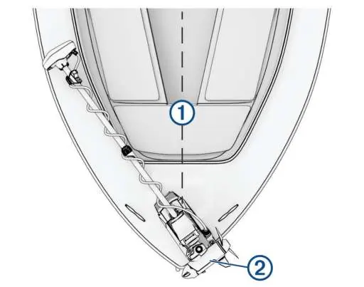
Before beginning, ensure you have the necessary tools: a drill with a 11/32 in. (9 mm) bit, #2 Phillips screwdriver, 4 mm hex bit/wrench, 1/2 in. (13 mm) socket, and a torque wrench. The motor must be installed on the bow of the boat, as close to the centerline as possible, with the mount overhanging the gunwale.
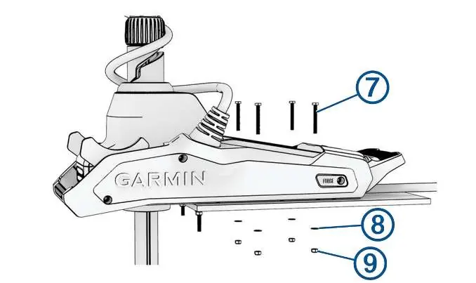
Mounting the Motor
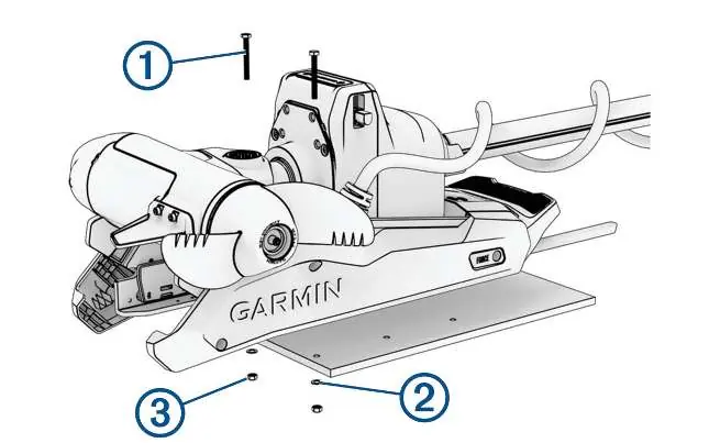
Use the included mounting template to mark hole locations on the deck. Drill the mounting holes using a 11/32 in. (9 mm) bit. Secure the mount to the deck using the provided bolts, washers, and locking nuts. For standard installation, use the six symmetrical holes; a minimum of four bolts is required if space is limited. Tighten the nuts to a torque of 14.9 N-m (11 lbf-ft.).
Electrical Connections
Connect the trolling motor to a 24 or 36 Vdc battery bank capable of supplying 60 A continuously. You must use a circuit breaker rated for 60 A. If extending the power cable, use single-conductor stranded wire with insulation rated for at least 75°C (167°F). Refer to the wire gauge chart in the manual to select the appropriate gauge based on the extension length.
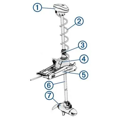
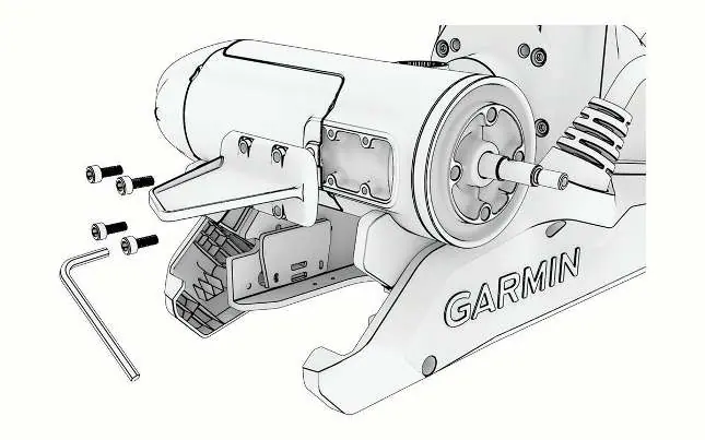
Propeller and Skeg Installation
Most models come pre-assembled. If required, install the nose cone and skeg using a 4 mm hex bit. To install the propeller, insert the pin through the motor shaft, align the propeller channel with the pin, and secure it with the anode, washer, lock washer, and nut. Tighten the lock nut to 16.27 N-m (12 lbf-ft) using a 9/16 in. (14 mm) socket.
Maintenance
After use in salt or brackish water, rinse the entire motor with fresh water and apply a water-based silicone spray. Avoid spraying water directly at the shaft cap. Periodically examine the coil cable for wear, lubricate the hinge with marine-grade grease, and clean or replace the anodes in the propeller drive motor.
Specifications
The motor operates on 20 to 45 Vdc with a 60 A continuous input. It features an IPX7 water rating for the steering motor and display panel housing, and IPX8 for the propeller drive motor. The remote control uses 2 AA batteries and operates on a 2.4 GHz frequency.
Manufacturer information
Garmin Ltd.
Practical help
Common problems
Motor does not lock in stowed position
Ensure the depth adjustment collar is moved as close to the base of the motor as possible.
Autopilot performance issues
Ensure no large metallic objects (e.g., tool boxes) are near the display panel when deployed, as they can interfere with the magnetic compass.
Power cable overheating or voltage drop
Ensure you are using the correct wire gauge (6, 4, or 2 AWG) based on the extension length as specified in the manual.
Before use
- Verify the boat deck is strong enough to support the motor weight and force.
- Ensure a 60 A continuous circuit breaker is installed.
- Check that the battery bank is 24 Vdc or 36 Vdc.
- Ensure all mounting bolts are tightened to 14.9 N-m (11 lbf-ft).
- Verify the propeller lock nut is tightened to 16.27 N-m (12 lbf-ft).
Specs in practice
- Input Voltage
- 20 to 45 Vdc required for operation.
- Input Amperage
- 60 A continuous current required.
- Compass Safe Distance
- 61 cm (2 ft.) distance required from the motor to avoid magnetic interference.
Images and diagrams
- Mounting template: Use to align the mount over the gunwale.
- Propeller assembly: Shows the sequence of the pin, propeller, anode, washer, lock washer, and nut.
Model compatibility
- Built-in transducer is compatible with select Garmin chartplotter models.
- Stabilizer is only included with the 90-inch Force Kraken model.

Manual page author
David Miller
Documentation analyst
Organizes user manual content into clear summaries, with attention to model details, product context, and everyday usability.