Tools / Generators
Generac 8 kW to 22 kW Air-Cooled Generator Owner's Manual
Comprehensive owner's manual for Generac 8 kW to 22 kW air-cooled standby generators, covering safety, operation, maintenance, and troubleshooting.
Table of contents
Product Overview
The Generac air-cooled generator is a high-performance, engine-driven unit designed to automatically supply electrical power to critical residential loads during a utility power failure. These units are factory-installed in all-weather metal enclosures intended exclusively for outdoor installation and operate on either vapor-withdrawn liquid propane (LP) or natural gas (NG).
Safety Rules
Safety is paramount when operating or servicing the generator. Users must read and understand the manual completely. Key hazards include carbon monoxide poisoning from exhaust, electrical shock from backfeed or live terminals, fire and explosion risks from fuel leaks, and mechanical hazards from moving parts. The generator must be installed outdoors with unobstructed ventilation. Never use the generator as a prime power source; it is intended for intermediate use during outages.
Operation
The generator features a control panel interface that allows for automatic, manual, or off operation. In AUTO mode, the system monitors utility power and automatically starts the generator during a failure. The unit includes a configurable exercise timer to ensure periodic operation. Users can manually transfer power if necessary, but must follow strict safety procedures to avoid electrical backfeed. The generator enclosure is lockable, and the side compartment houses the main circuit breaker and LED status indicators.
Maintenance
Regular maintenance is essential for performance and longevity. The service schedule includes daily checks for debris and leaks, as well as periodic tasks like oil and filter changes, air cleaner replacement, spark plug maintenance, and valve clearance adjustments. Emissions-critical maintenance must be performed as scheduled to maintain warranty compliance. Owners should perform visual inspections for corrosion and keep the enclosure clean using mild soap and water.
Troubleshooting
The system includes diagnostic alarms to alert the operator to faults. Common issues such as engine cranking failures, starting difficulties, or lack of power output can often be resolved by checking the fuel supply, battery condition, circuit breakers, or air cleaner. If an alarm occurs, the control panel will display the fault, and users should follow the provided troubleshooting guide or contact an Independent Authorized Service Dealer for professional assistance.
Storage and Disposal
If the generator will be out of service for more than 90 days, follow the specific removal from service procedure, which includes draining the oil, disconnecting the battery, and protecting the engine. Always recycle batteries and used oil at authorized collection centers in accordance with local regulations.
Manufacturer information
Generac Power Systems, Inc.
Practical help
Common problems
Engine will not crank
Check for a blown fuse, loose/corroded battery cables, or a dead battery.
Engine cranks but will not start
Check for fuel supply, clean or replace spark plugs, or reset valve clearance.
No AC output
Ensure the main line circuit breaker is in the ON (CLOSED) position.
Unit shuts down during operation
Check for high temperature, overload, or low oil pressure alarms.
Before use
- Verify all shrubs/grass are cleared within 3 ft of the enclosure.
- Ensure all water sources are directed away from the generator.
- Check engine oil level.
- Verify the main circuit breaker is in the ON position.
- Ensure the control panel is set to AUTO mode.
- Check for any fuel or oil leaks.
Specs in practice
- Rated Voltage
- The standard output voltage for the generator, which is 240V.
- Battery Requirement
- Group 26R, 12V, 540 CCA minimum battery is required for starting.
- Normal Operating Range
- Tested for operation between -20 °F (-29 °C) and 122 °F (50 °C).
- Valve Clearance
- The gap between the rocker arm and valve stem, specified at 0.05-0.1 mm (0.002-0.004 in).
Images and diagrams
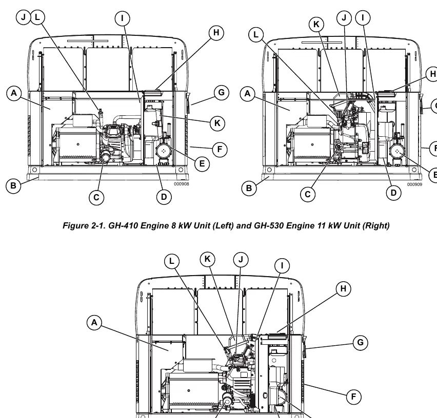
- Figure 2-1/2-2: Identifies key components like the oil filter, battery compartment, fuel regulator, and control panel.
- Figure 3-1: Shows the side compartment with the main circuit breaker and LED indicators.
- Figure 3-4: Illustrates the control panel interface buttons (AUTO, MANUAL, OFF).
- Figure 4-1: Provides the recommended oil viscosity chart based on ambient temperature.
- Figure 4-4: Details the valve clearance adjustment points.
Model compatibility
- Compatible with vapor-withdrawn liquid propane (LP) or natural gas (NG).
- Cold weather kit recommended for temperatures below 32 °F (0 °C).
- Requires an approved transfer switch for connection to building electrical systems.
- Not intended for critical life support applications.

Manual page author
Michael Turner
Technical manual editor
Reviews PDF manuals for structure, safety notes, and practical product details so readers can find the right information quickly.