Tools / Laser Engraving Accessories
User Manual for Genmitsu 101-63-FLRR Upgraded Laser Rotary Roller
Quick guide for the Genmitsu 101-63-FLRR Upgraded Laser Rotary Roller. Learn how to adjust roller distance, set up for cylinder engraving, use the Y-bracket for tapered objects, and connect the stepper motor cables.
Table of contents
Manual images
Click an image to enlargeQuick guide from the manual
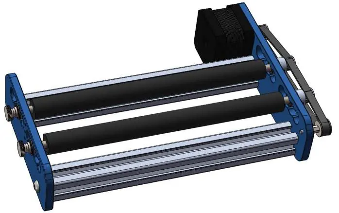
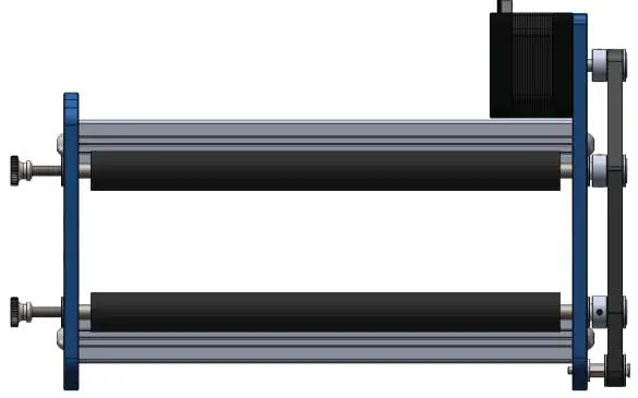
The Genmitsu 101-63-FLRR Upgraded Laser Rotary Roller is designed for engraving on cylindrical objects. It is compatible with most laser engravers and cutters on the market. The device features an adjustable roller distance and supports a maximum load weight of 10KG.
Package List
- 1x Laser Rotary Roller
- 1x Y-bracket
- 2x M3 x 12mm Thumbscrews
- 3x M3 Nylon Gaskets
- 1x Regular Stepper Motor Extension Cable (A+A-B+B-)
- 1x Crossover Stepper Motor Extension Cable (A+B+A-B-)
- 1x User Manual
Adjusting Roller Distance
If the distance between the two rollers is insufficient for your material, follow these steps:
- Loosen the M4 thumbscrews counterclockwise until the distance between the thumbscrew and the left bracket plate is 12mm.
- Pull up the right synchronous belt to remove it from the synchronous wheel groove.
- Push both rollers to the right simultaneously so the bearings exit the limit holes on the right bracket plate.
- Pull the bearings out of the left bracket plate.
- Adjust the rollers to the desired distance, ensuring both sides are positioned equally.
- Re-install the bearings into the limit holes, push the rollers back into place, tighten the M4 thumbscrews, and reinstall the synchronous belt.
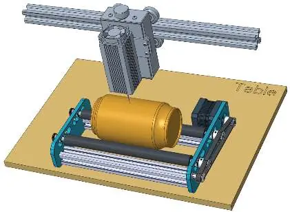
Guide on Engraving Cylinder
1. Place the rotary roller on a flat surface under your laser engraver, ensuring enough space to avoid collisions.2. Position the roller so the highest point of the material is directly below the laser beam, with the axis of rotation parallel to the laser head moving direction.3. Adjust the laser head focal distance according to the highest point of the material.
Guide on Engraving Material Like Wine Glass
For tapered objects, use the included Y-bracket:
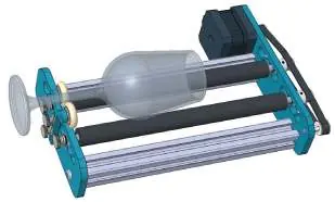
- Insert M3 hand-screws through the nylon spacer and Y-bracket, then screw them into the left bracket plate.
- Place the larger diameter end of the material between the rollers and the smaller end between the round pulleys.
- If the Y-bracket movement is restricted, remove the thumbscrews and select different threaded holes from the four available on the Y-bracket.
- Ensure the axes of rotation are parallel to the laser head movement.
Wire Connection
1. Choose the correct extension cable based on your machine's wire sequence.2. If the laser head moves along the X-axis, unplug Y-axis stepper motor cables and connect the rotary roller using the extension cable.3. If the laser head moves along the Y-axis, unplug X-axis stepper motor cables and connect the rotary roller using the extension cable.4. Turn on the machine and test the motor operation.
Practical help
Common problems
Rollers do not move in synchronization or movement is not smooth
Check if the synchronous belt is properly seated in the groove and adjust the shaft again.
Y-bracket movement is restricted
Remove the M3 thumbscrews and choose two suitable threaded holes from the four available on the Y-bracket.
Before use
- Ensure the synchronous belt is properly seated in the groove of the synchronous wheel.
- Rotate one roller by hand to ensure the other rotates smoothly.
- Verify the material is non-reflective to avoid laser damage.
- Ensure the axis of rotation is parallel to the laser head moving direction.
- Check that the laser head focal distance is adjusted to the highest point of the material.
Specs in practice
- Maximum Load Weight
- 10KG
- Engraving Size
- Cylinder diameter 5mm - 160mm, length 10mm - 195mm
- Adjustable Range
- 19mm - 76mm
Images and diagrams
- Roller spacing adjustment involves loosening M4 thumbscrews and moving bearings out of limit holes.
- Y-bracket installation requires M3 hand-screws, nylon spacers, and selecting appropriate threaded holes.
- Wiring requires choosing between Regular or Crossover extension cables based on the controller's wire sequence.
Model compatibility
- Works with most laser engravers and laser cutters on the market.

Manual page author
Michael Turner
Technical manual editor
Reviews PDF manuals for structure, safety notes, and practical product details so readers can find the right information quickly.