Electronics / Video Transmission
Gofanco PRO-SDIGen 12G/6G/3G/HD/SD-SDI Pattern Generator
Quick guide for the Gofanco PRO-SDIGen pattern generator. Learn how to connect, operate, and use the device for SDI signal testing and calibration.
Table of contents
Manual images
Click an image to enlargeQuick guide from the manual
The Gofanco PRO-SDIGen is an advanced SDI pattern generator designed for testing and calibrating SDI-enabled video devices and displays. It supports multi-format signals (12G/6G/3G/HD/SD) and provides various video test patterns and audio support. This guide covers the essential setup, operation, and technical specifications for the device.
Safety Information
- Do not attempt to service the unit yourself.
- Ensure proper ventilation and air circulation; do not use near water.
- Place the unit on a stable surface.
- Use only the provided power adapter and compatible connection cables.
- Always unplug the device before cleaning; do not use liquid or aerosol cleaners.
Panel Description
The device is equipped with physical controls and ports for easy operation:
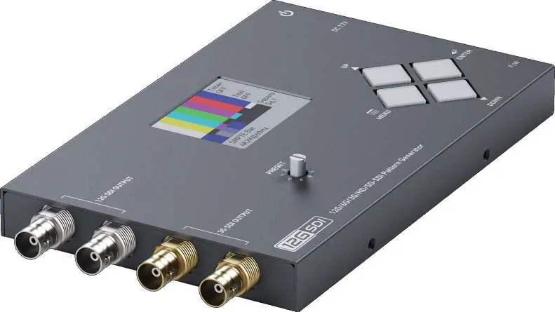
- SDI OUT1-2: High-bandwidth outputs supporting 12G/6G/3G/HD/SD-SDI.
- SDI OUT3-4: Outputs supporting 3G/HD/SD-SDI.
- Rotary Switch: Used to select between 0-7 preset modes.
- LCD Monitor: 2.0-inch display for monitoring and menu navigation.
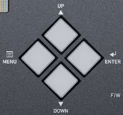
- Push Buttons: Includes Menu (opens OSD), Enter (selects item), Up, and Down buttons for navigation.
- Micro USB: Port reserved for firmware updates.
- Power Switch: Turns the device ON/OFF.
- +12V DC: Power input jack.
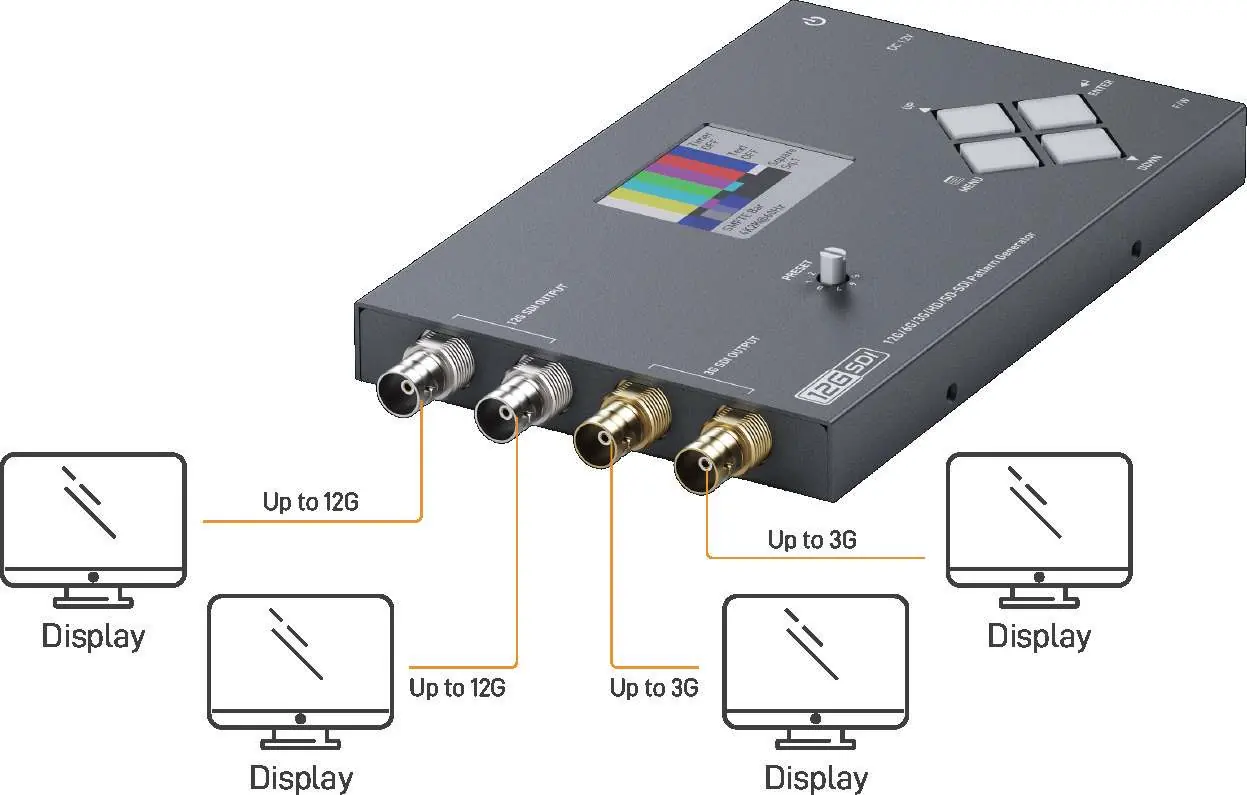
Connection Diagram
For optimal signal integrity, it is strongly recommended to use only one SDI output with a 75-ohm cable. Connect your display devices to the appropriate SDI output ports based on the required bandwidth (up to 12G or 3G).
Operating Instructions
The device is controlled via the front panel buttons and the rotary switch. Use the Menu button to access the On-Screen Display (OSD) and the Up/Down buttons to navigate through settings. The Rotary Switch allows for quick selection of preset modes (0-7). Settings can be saved to the memory option.
Technical Specifications
- Supported Protocols: SMPTE 259M, 292M, 424/425M, ST-2081, ST-2082.
- Video Support: Up to 11.88Gbps.
- Resolution Support: Includes 4K2K (up to 60Hz), 1080p, 1080i, 720p, NTSC, and PAL.
- Power Supply: 12VDC.
- Power Consumption: 5 Watts (max).
- Operating Temperature: 0 to 40°C (32 to 104°F).
- Dimensions: 167 x 112 x 24mm.
- Weight: 303g.
Package Contents
- 1x PRO-SDIGen Pattern Generator
- 1x 12V Power Supply Unit
- 1x User Manual
Practical help
Common problems
Device does not power on
Ensure the 12V DC power supply is securely connected to the power jack and the power switch is in the ON position.
No signal on the connected display
Verify that the SDI cable is securely connected and that the display supports the output resolution/format selected on the generator.
Signal quality issues
Ensure you are using a high-quality 75-ohm SDI cable. It is recommended to use only one SDI output at a time for high-frequency bandwidth signals.
Before use
- Place the unit on a stable, flat surface.
- Ensure the area has proper ventilation.
- Verify the power adapter is the one supplied with the unit.
- Check that the SDI cables are 75-ohm compliant.
- Ensure the power switch is OFF before connecting the power supply.
Specs in practice
- Rotary Switch
- A physical dial used to quickly cycle through 8 preset modes (0-7).
Images and diagrams
- SDI OUT1-2: Primary outputs for high-bandwidth signals up to 12G.
- SDI OUT3-4: Secondary outputs for signals up to 3G.
- Push Buttons: Central interface for OSD navigation and selection.
Model compatibility
- Recommended to use only one SDI output with one 75-ohm cable for best signal performance.
- Features such as timings and test patterns may change due to firmware updates.

Manual page author
David Miller
Documentation analyst
Organizes user manual content into clear summaries, with attention to model details, product context, and everyday usability.