Lighting / LED Lamps
Installation Guide for Green Creative LED PLL Retrofit Kit
Installation guide for Green Creative LED PLL retrofit kits. Includes wiring diagrams for 1 and 2 lamp configurations, safety warnings, and luminaire compatibility requirements.
Quick answers from the manual
Quick answer
- This manual provides instructions for retrofitting fluorescent luminaires with Green Creative LED PLL tubes. It requires bypassing the existing ballast and wiring the tubes directly to the line voltage (120-277V). p. 1, 3
Key actions
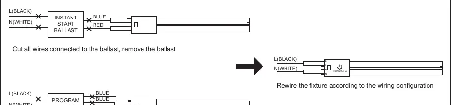
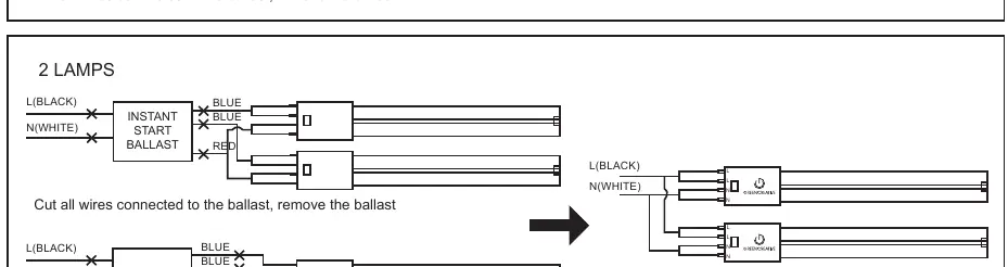
- Cut all wires connected to the ballast and remove the ballast. p. 3
- Connect Line (L) and Neutral (N) to the corresponding ends of the tube. p. 3
First start
- Turn off power, remove old components, wire according to the diagram, and affix the modification sticker. p. 3
Technical specifications
| Parameter | Value | Meaning | Pages |
|---|---|---|---|
| Input Voltage | 120-277V | Operating voltage range | p. 1 |
Where to find it in the PDF
- Safety Warnings and Dimensions p. 1
- Installation Steps and Wiring Diagrams p. 3
Table of contents
Manual images
Click an image to enlargeQuick guide from the manual
This document provides installation instructions for Green Creative LED PLL retrofit kits. The installation requires bypassing the existing ballast. The product is double-ended, meaning Line (L) and Neutral (N) must be connected to the corresponding ends of the tube. Installation must be performed by a qualified electrician.
Safety Warnings
- Risk of fire or electric shock: Installation requires knowledge of luminaire electrical systems.
- Power: Disconnect power at the source before installation. Do not simply switch off the fixture.
- Compatibility: Not for use with dimmers, emergency exit fixtures, or luminaire ballasts.
- Wiring: Do not make or alter any open holes in the enclosure of wiring or electrical components during installation.
- Modification: The luminaire must be marked with a "This luminaire has been modified to operate LED lamps" sticker, visible during normal maintenance.
Installation Requirements
The retrofit kit is intended for surface mount, Type IC, or non-IC recessed mount fluorescent luminaires. Minimum luminaire dimensions vary by model:
- 17PLL/16PLL models: Minimum lamp compartment dimensions are 61.5cm (L) x 60.5cm (W) x 10.5cm (H). Maximum 3 lamps.
- 10PLL/8.5PLL models: Minimum lamp compartment dimensions are 44cm (L) x 14cm (W) x 10cm (H). Maximum 2 lamps.
Installation Steps
- Read all warnings before starting.
- Ensure power is turned off at the source.
- Remove the lens, cover, and existing fluorescent tubes.
- Cut all wires connected to the ballast and remove the ballast.
- Connect the Line (L) and Neutral (N) to the corresponding ends of the tube marked L and N. Note: This product is double-ended; do not wire to a single end.
- Follow the specific wiring diagrams provided in the manual for the number of lamps and original ballast type.
- Affix the "Modification Sticker" to the fixture.
- Reinstall the housing cover and lens if applicable.
- Return power to the source.
Wiring Configurations
The manual provides specific wiring diagrams for 1-lamp and 2-lamp configurations, detailing how to bypass Instant Start and Program Start ballasts. Ensure all wires connected to the ballast are cut and the ballast is removed before rewiring the fixture according to the provided diagrams.
Practical help
Common problems
Fixture uses a dimmer
This product is not for use with dimmers.
Emergency exit fixture
This product is not intended for use with emergency exit fixtures or lights.
Ballast compatibility
This product is not for use with a luminaire ballast; the ballast must be removed.
Before use
- Ensure power is turned off at the source.
- Verify the luminaire dimensions meet the minimum requirements listed in the manual.
- Ensure the installation is performed by a qualified electrician.
- Confirm the fixture is not an emergency exit type.
- Ensure the fixture does not use a dimmer.
Specs in practice
- Input Voltage
- Rated for 120-277V. Installer must verify line voltage before installation.
Images and diagrams
- Wiring diagrams illustrate how to bypass the ballast for 1-lamp and 2-lamp fixtures.
- Diagrams show connections for both Instant Start and Program Start ballast configurations.
Model compatibility
- Suitable for damp locations.
- Suitable for use in wet locations when used in an outdoor-rated fixture.
- Not for use where directly exposed to weather or water.

Manual page author
David Miller
Documentation analyst
Organizes user manual content into clear summaries, with attention to model details, product context, and everyday usability.