Home Appliances / Small Kitchen Appliances
Installation Manual for Westinghouse 18W T8 U-Bent LED Light Bulb
Installation guide for the Westinghouse 18W T8 U-Bent LED Light Bulb. Includes wiring diagrams for ballast bypass, dimming module setup, and safety precautions for retrofit installation.
Quick answers from the manual
Quick answer
- This manual covers the installation of the Westinghouse 18W T8 U-Bent LED Light Bulb, specifically for ballast bypass retrofits. It includes wiring diagrams for 1, 2, and 4-lamp configurations and instructions for 0-10V dimming. p. 3, 4
Key actions
- Bypass the electronic ballast and wire the LED tube directly to the AC power source. p. 3, 4
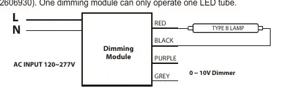
- Install the Westinghouse dimming module (502606930) for 0-10V dimming control. p. 4
First start
- Switch off the power supply, bypass the ballast, and connect the LED tube according to the provided wiring diagrams. p. 3
Problems and fixes
Lamp does not dim correctly
Ensure you are using the Westinghouse dimming module 502606930; standard dimmers are not compatible.
p. 4Technical specifications
| Parameter | Value | Meaning | Pages |
|---|---|---|---|
| Input Voltage | 120-277V | Operating voltage range | p. 3, 4 |
| Minimum Compartment Dimensions | 605x604x81mm | Required space for installation | p. 5 |
Where to find it in the PDF
- Wiring Instructions p. 3, 4
- Dimming Function p. 4
Table of contents
Manual images
Click an image to enlargeQuick guide from the manual
This document provides installation instructions for retrofitting existing fluorescent luminaires with the Westinghouse 18W T8 U-Bent LED Light Bulb. The installation requires bypassing the existing electronic ballast. Important: This product must be installed by a qualified electrician. It is not intended for emergency lighting.
Product Features and Applications
The LED bulb features a full glass housing that resists aging, yellowing, and bending. It is UL certified and suitable for use in residential buildings, offices, shopping malls, supermarkets, hospitals, assembly lines, and warehouses.
Installation Instructions
The installation involves a ballast bypass procedure. Ensure the power supply is switched off before commencing any work. Installers must not disconnect existing wires from lampholder terminals to make new connections; instead, cut existing lampholder leads away from the ballast and make new electrical connections using applicable connectors.
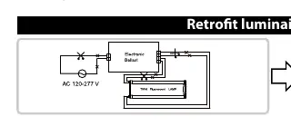
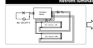
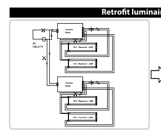
Wiring Configurations
The manual provides specific wiring diagrams for retrofitting luminaires with 1, 2, or 4 lamps. In all configurations, the electronic ballast is bypassed, and the lamps are connected directly to the AC 120-277V power source.
Dimming Function
This tube supports 0-10V dimming when installed in combination with the Westinghouse dimming module (model 502606930). One dimming module can operate only one LED tube. The lamp will not operate properly if connected to a standard incandescent dimmer or dimming control.
Safety Precautions
- Shunted Lampholders: Do not use this retrofit kit in luminaires employing shunted bi-pin lampholders, which are typically found in fluorescent luminaires with Instant-Start ballasts (marked as "Instant Start" or "I.S.").
- Electrical Safety: Risk of fire or electric shock. Do not make or alter any open holes in an enclosure of wiring or electrical components during installation.
- Compatibility: Ensure the luminaire construction features and dimensions match the requirements (minimum compartment dimensions: 605x604x81mm).
Practical help
Common problems
Incompatible Dimming
The lamp will not work with standard incandescent dimmers. You must use the specific Westinghouse dimming module (model 502606930).
Shunted Lampholders
Do not install in luminaires with shunted bi-pin lampholders (common in Instant-Start ballasts). Check for 'Instant Start' or 'I.S.' markings on the ballast.
Installation Safety
Installation must be performed by a qualified electrician. Always switch off the power supply before starting.
Before use
- Verify the luminaire is not for emergency lighting.
- Ensure the ballast is not an Instant-Start type with shunted lampholders.
- Confirm the luminaire compartment dimensions are at least 605x604x81mm.
- Switch off the main power supply.
- Have the correct connectors ready for wiring.
Specs in practice
- Ballast Bypass
- The existing electronic ballast is removed from the circuit, and the LED tube is wired directly to the AC power.
- 0-10V Dimming
- A specific control method requiring an external dimming module to adjust light intensity.
Images and diagrams
- Wiring diagrams illustrate the removal of the electronic ballast and direct connection of the LED tubes to the AC 120-277V line and neutral wires.
Model compatibility
- Compatible with surface mount or recessed fluorescent luminaires.
- Not for use with emergency lighting.
- Requires specific Westinghouse dimming module 502606930 for dimming functionality.

Manual page author
David Miller
Documentation analyst
Organizes user manual content into clear summaries, with attention to model details, product context, and everyday usability.